
If you want to know about the site planning and development for disabled persons or wheelchair user accessible toilet design or disabled parking space, please click the link.
Site planning and development for disabled persons is an important aspect of creating an inclusive and accessible built environment.
- Site development is the most effective means to resolve the problems created by topography, definitive architectural designs or concepts, water table, existing streets, and typical problems, singularly or collectively, so that ingress and egress to buildings by persons with disabilities can be facilitated while preserving the desired design and effect of the architecture.
- Each building and its site shall be planned and designed as an integral unit from the very beginning of the design process.
- Equipment and materials causing allergic reactions shall as far as possible be avoided in dwellings and buildings.
- The provisions of accessibility in outdoor built environment covered herein pertain to the immediate outdoor environment of a building or of a building complex.
- However, these may be considered by the Authorities and concerned parties for suitably applying the same at township/city level.
1) Walkways and pathways
Walkways and pathways (used here interchangeably) shall meet the following general requirements:
- Walkways shall be smooth, hard and have levelled surface suitable for walking and wheeling. Irregular surfaces as cobble stones, coarsely exposed aggregate concrete, bricks, etc., often cause bumpy rides and shall be avoided.
- Minimum walkway width shall be provided as per “Width of the Walkway/Pathway” (given below). The width of footpath shall be in accordance with Footpaths and Pathways (please click this link).
- The walkway shall not have a gradient exceeding 1:20. If the slope or any part of a walkway on an accessible route to a building exceeds 1:20, it shall be designed and constructed as a ramp in accordance with Ramps (please click this link).
- Where pathway meets the road, a kerb shall be provided, which shall be designed in accordance with “Levels, grooves, gratings and manholes” (given below).
- The cross-fall gradient across an accessible route shall not exceed 1:50 (20 mm/m), except when associated with a dropped kerb.
- The requirements for drainage of pathways shall be as per “Drainage of path/access routes” (given below).
- When walkways exceed 60 m in length, it is desirable to provide rest area adjacent to the walk at convenient intervals of 30 m in the form of benches/resting seats. For comfort, seat height shall be between 450 mm and 500 mm, and the seating shall have a back rest and arm rests at 700 mm height. One side of seating may be without arm rest to address the transfer needs of persons with disabilities. A colour contrast should be provided around the seating area for ease of identification by persons with low vision.
- Texture change in walkways adjacent to seating shall be provided for persons with vision impairment by means of warning blocks (see “Tactile Ground Surface Indicators (TGSI)” (given below)).
- Gratings and manholes should be avoided in walks.
- Walks or driveways shall have a non-slip surface. Care shall be taken to ensure that adjacent surface materials do not display different slip resistance characteristics, particularly at the edges of changes of level or gradients.
- Such walks shall be of a continuing common surface not interrupted by steps or abrupt changes in level.
- Wherever walks cross other walks, driveways, or parking lots, they shall blend to a common level.
- Obstacles, such as objects or signs mounted on walls, columns or free-standing supports along the walking path shall be avoided. These shall however be regulated in accordance with (see E-a (given below)). Bollards along or on the walking pathway shall also be regulated in accordance with (see E-a (given below)). Any protruding object projecting into a walkway shall be treated in accordance with (see “Protruding Objects” (given below)).
i) Width of the Walkway/Pathway
The unobstructed width of the pathway shall be,
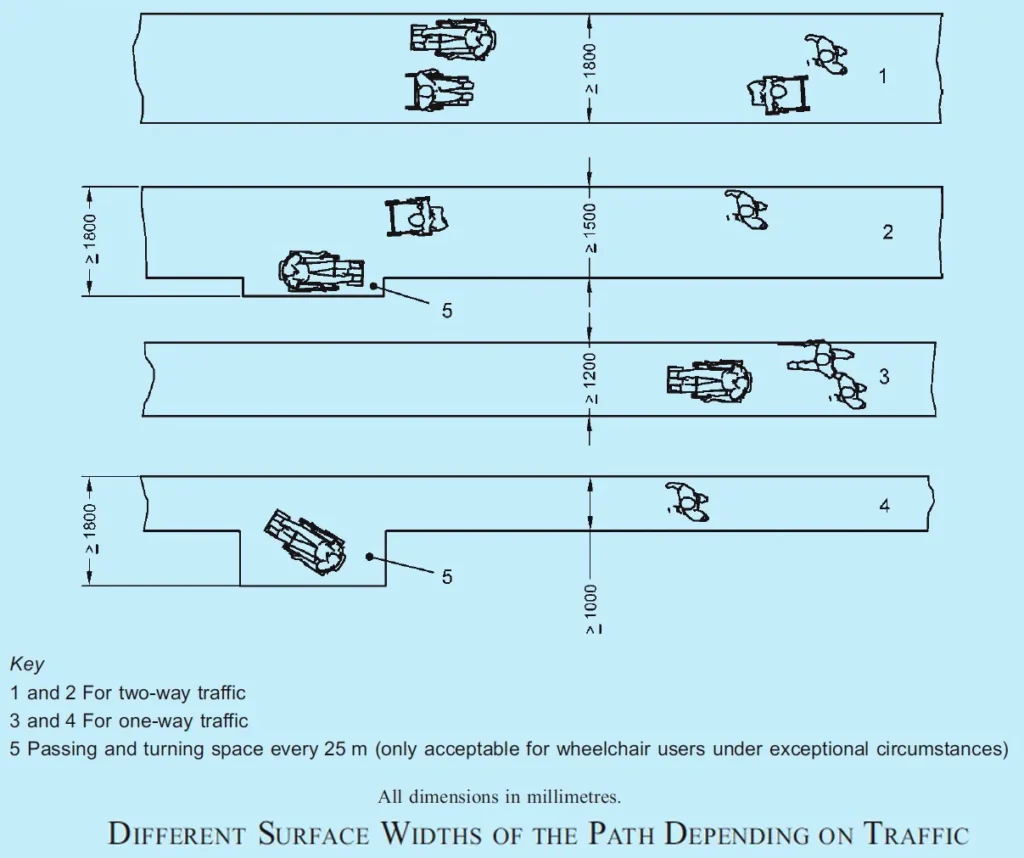
- Not less than 1800 mm for two-way traffic (see key 1 of Figure above); which may be reduced to a minimum of 1500 mm, provided that a passing and turning space of at least 1800 mm × 2000 mm should be provided for every 25 m (see keys 2 and 5 of Figure above); and
- Not less than 1200 mm for one-way traffic (see key 3 of Figure above); which may be reduced to a minimum of 1000 mm, provided that a passing and turning space of at least 1800 mm × 2000 mm should be provided for every 25 m (see keys 4 and 5 of Figure above).
- The width of footpath shall be in accordance with Footpaths and Pathways (please click this link).
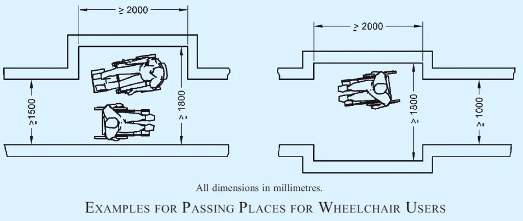
ii) Passing space for wheelchair users
- A path whose surface width is less than 1800 mm (see above points) and whose overall length is more than 50 m, shall be provided with a passing place or places.
- Passing places should be a maximum of 25 m apart.
- This does not apply to a landing forming part of a sloped path, a ramp, steps or a stair.
- Passing place for two people using wheelchairs shall be a minimum width of 1800 mm for a minimum length of 2000 mm as seen below figure.
Note
- Passage widening can be associated with intersections, turns and doorways so as to appear as integrated design features or enhancements.
- A-2a) For wheelchair manoeuvrability at turnings, minimum turning radius shall be required in accordance with Turning Space for 90° Turn of a Wheelchair in Corridors and Circulation Space for 180° Wheelchair Turn (please click this link).
iii) Stepped path and stair
- For ambulant people, a stepped path can provide a safer and more assuring means of access than a sloped path or a ramp.
- Wherever the rise of a ramp exceeds 300 mm, an additional flight of steps shall also be provided.
- An isolated single step is not acceptable.
- Where required on a continuous accessible path of travel, tactile warning indicators shall be located at both the top and bottom of stairways.
- The surface width of a stepped path and stair shall be not less than 1200 mm and it shall meet the other requirements of Stairs (please click this link).
iv) Support and guidance by a handrail on paths
- Support and guidance by a handrail shall be provided on stepped paths.
- A handrail shall be provided on each side of a flight of steps consisting of two or more risers and each riser shall be not more than 150 mm high.
- A handrail shall be provided on both sides of a channel that can subdivide a flight of steps.
- For requirements of handrails, reference shall be made to Specific Requirements for Handrail (please click this link).
v) Drainage of path/access routes
- The cross-fall of a level or sloped path, a stepped path, a ramp, or a landing, that is provided to permit drainage of surface water, shall be in accordance with (v) (given above).
- The top, bottom and landings of steps and ramps shall be properly drained in order to avoid water flowing down steps and ramps.
- A dished channel should not be constructed within the boundaries of a path or ramp.
- Dished channels shall have a maximum width of 150 mm and a maximum drop into gulley of 5 mm.
- A drainage grating that is within the boundaries of a path or a ramp shall be set flush with the surface (Levels, grooves, gratings and manholes (given below)).
vi) Guarding along paths and ramps
- Providing protection at the side of the path protects people who use wheelchairs and ambulant people from injuring themselves as the result of a fall.
- Examples of protection against falling are shown in Figure below.
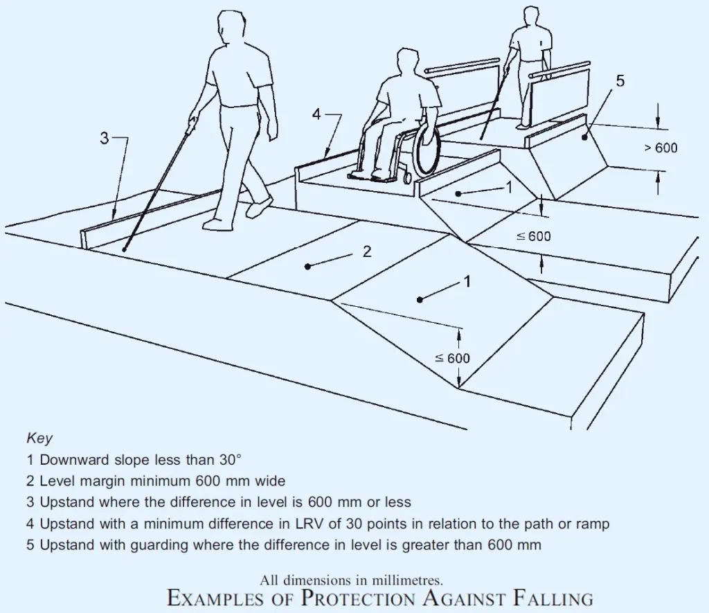
- If a level or sloped path is bounded on one or both sides by terrain that slopes downwards by up to 30° from the horizontal, a firm and level margin of at least 600 mm shall be provided at the relevant side or sides.
- If a sloped path or ramp is bounded on one or both sides by terrain that slopes downwards by more than 30°, an upstand of minimum height of 150 mm shall be provided at the relevant side or sides. Upstands shall have a minimum difference in LRV of 30 points in relation to the ramp.
- If a path, or a sloping path, stepped path, ramp, terrace or other unfenced platform rises more than 600 mm above the adjacent ground, it shall be provided with guarding. If the adjacent ground is firm and level with the path for 600 mm, no guard is needed. Guarding shall be designed to discourage a user, particularly a child, from climbing on it.
2) Kerb ramp/dropped Kerb
- It is a ramp built on a footpath or pavement to accommodate the change in level towards vehicular areas to allow easy and continuous access.
- Kerb ramps shall be provided at pedestrian crossings and at each end of the footpath of a private street or access road.
- Kerb ramps shall be provided where the vertical rise is less than 150 mm.
They shall meet the following requirements:
- They shall have a slip-resistant surface.
- They shall avoid raised traction strips in order to reduce the hazard to everyone.
- They shall be designed not to allow water accumulating on the walking surface.
- Handrails may not be provided with kerb ramps.
- They shall not project into the road surface.
- They shall be so located and also protected to prevent obstruction by parked vehicles.
- They shall be free from any obstruction such as signposts, traffic lights, etc.
- They shall not encroach into a roadway, as it is dangerous for users and obstructive for vehicles.
- They shall be so located to enable users to have an unobstructed view of traffic approaching from any direction.
- They shall be provided with adequate visual and tactile warning.
- TGSI (warning type) shall be provided to notify the presence of traffic and shall have a minimum luminous contrast of 70 percent with the adjoining surfaces for the elderly and persons with visual impairment.
Typical kerb ramp requirements and kerb extension at street intersections are shown in Figure below.
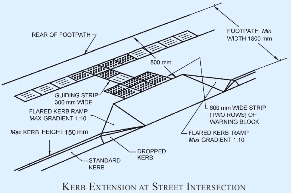

i) Gradient
- The gradient of a kerb ramp shall not be steeper than 1:12.
ii) Width
- The kerb ramp shall not be less than 1200 mm in width.
- It shall provide a clearance of at least 800 mm at the back of the kerb ramp on the footpath as shown in figure below.
iii) Flared Sides
- Kerb ramps shall have flared sides where pedestrians are likely to walk across them as shown in Figure above and the gradient of the flared side shall not be steeper than 1:10.
3) Levels, grooves, gratings and manholes
i) Passing over Different Levels and Grooves
- Vertical level changes up to 6 mm may not need edge treatment.
- Changes in level between 6 mm and 12 mm shall be levelled off with a slope no greater than 1:2.
- The edge shall be rounded off or bevelled.
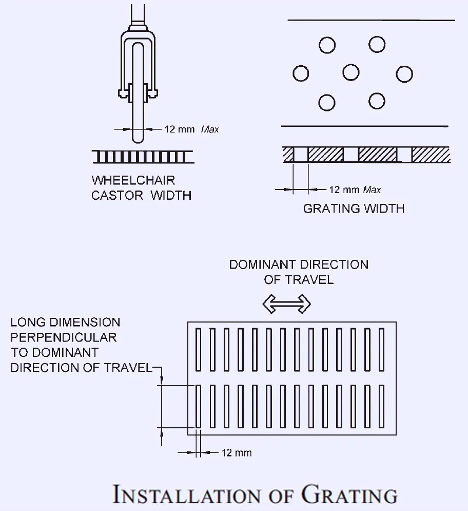
ii) Gratings and manholes
- Gratings and manholes should be avoided on walkways/ pathways.
- If unavoidable, gratings shall have spaces not greater than 12 mm wide in one direction to prevent a wheelchair from getting its casters caught in a drainage ditch or grating cover.
- Also, the grating bars shall be perpendicular to the travel path in such a way that its longer dimension is perpendicular to the dominant direction of movement.
- Grating shall be flushed with finished ground level and shall be treated with a non- slip finish as shown in the figure below.
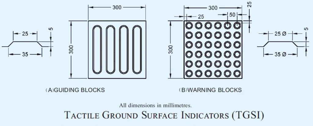
4) Tactile Ground Surface Indicators (TGSI) — Tactile Guiding and Warning Blocks
- Tactile ground surface indicators or tactile guiding and warning tiles/blocks aid blind and vision impaired pedestrians negotiate the built environment, and shall be of the dimensions as given in Figure below
Note
- Alternatively, other internationally accepted tactile pattern may be accepted by the Authority.
- D-a) Tactile guiding blocks indicate a correct path/ route to follow for a person with visual impairment. It is recommended to install one/two rows of tactile guiding blocks along the entire length of the proposed accessible route. Care shall be taken to ensure that there are no obstacles, such as trees, poles or uneven surfaces, along the route traversed by the guiding blocks. Also, there shall be clear headroom of at least 2100 mm height above the tactile guiding blocks, free of protruding objects such as overhanging tree branches and signage, along the entire length of the walk.
- D-b) Tactile warning blocks indicate an approaching potential hazard or a change in direction of the walkway, and serve as a warning of the approaching danger to persons with visual impairments, preparing them to tread cautiously and expect obstacles along the travel path, traffic intersections, doorways, etc. They are used to screen off obstacles, drop-offs or other hazards, to discourage movement in an incorrect direction, and to warn of a corner or junction. Two rows of tactile warning tiles shall be installed across the entire width of the designated accessible pathway, before intersections, building entrances, level changes, obstacles such as trees, and each time the walkway changes direction. Warning blocks shall be placed 300 mm from the beginning and end of the ramps and stairs, at landings and entrance to any door.
i) Places to Install TGSI (see Figure below)
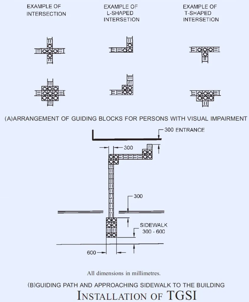
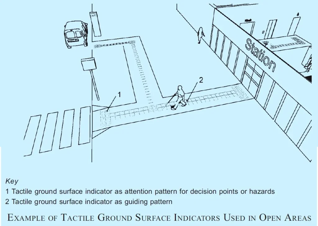
TGSI shall be installed at following places:
- In open space to orient persons with vision impairment.
- In front of an area where traffic is present.
- In front of an entrance/exit to and from a ramp, staircase or multi-level crossing facility.
- Entrances/exits at public transport terminals or boarding areas.
- Sidewalk/footpath section of an approach road to a building; and
- From a public facility to the nearest public transport station.
5) Barriers and hazards
- E-a) Obstacles, such as objects or signs mounted on walls, columns or free-standing supports along the walking path shall be avoided.
- Unavoidable free-standing posts or columns within access routes on pathways shall leave at least unobstructed walking width of 1000 mm and be clearly marked with visual indicators.
- Visual indicators at least 75 mm in height with a minimum visual contrast of 30 points difference in the LRV value of the colours to the background shall be placed; one at a height between 800 mm and 1000 mm above floor level, and the other between 1400 mm and 1600 mm above floor level.
- Bollards, short vertical posts generally arranged in a line to guide traffic and protect from vehicle intrusions, shall have a maximum height of 1000 mm.
- Bollards, where installed within the access route shall have a minimum clear spacing between them of 1000 mm so as to provide clear passage width for movement of wheelchairs.
i) Protruding Objects
- Unavoidable protruding objects shall not reduce the minimum clear width of an accessible route or manoeuvring space.
- Protruding objects in the access route shall contrast visually with the background environment.
- Objects with a height lower than 1000 mm can create a hazard for blind or partially sighted people.
- Permanent equipment that cannot be located outside the boundaries of a path shall be,
- i) designed to be easily seen with a minimum difference in LRVs of 30 points to the background.
- ii) shielded to protect against impact; and
- iii) accompanied by a feature that warns of the presence of a potential hazard and is detectable for a person using a white cane or stick as given figure below.
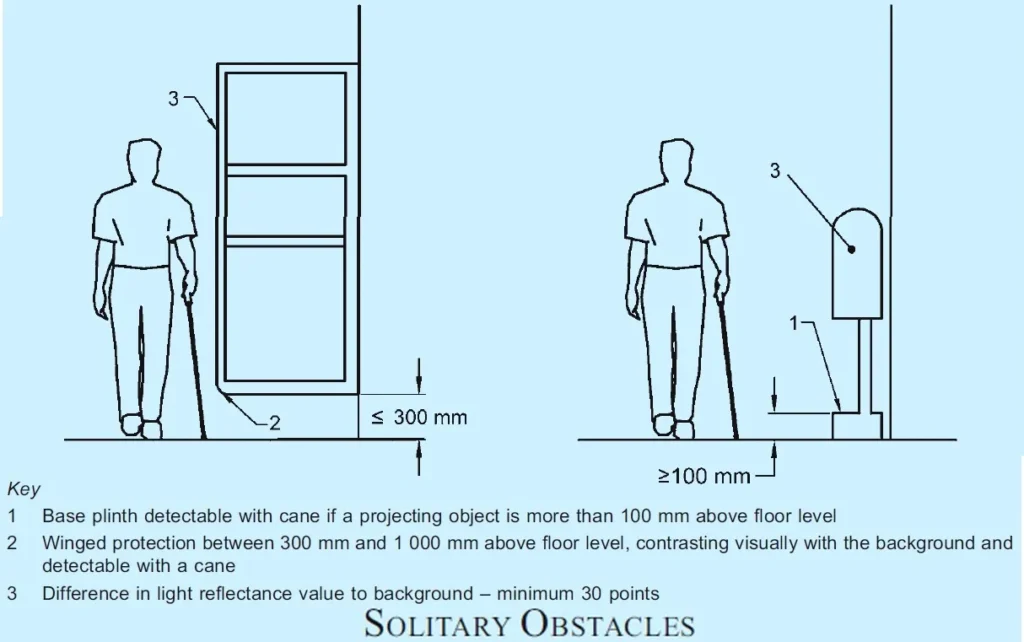
- The headroom along a path shall be maintained at a height of not less than 2100 mm above the surface of the path.
- Any objects projecting more than 100 mm between 300 mm and 2100 mm above ground level into an access route shall be clearly visible and detectable with a cane (see Figure above).
- When a projecting obstacle exists, a protective guard shall be provided at ground level, under the projecting object, such as, a kerb or fixed element at a height of 100 mm-300 mm as cane detection.
- Cane detection shall not be set back more than 100 mm from the face of the projecting object.
- Wing walls, side partitions, alcoves or recesses are solutions for projecting elements where free space under the object is needed.
- Winged protection shall extend continuously between 300 mm and 1000 mm above the floor and shall contrast visually with the background.
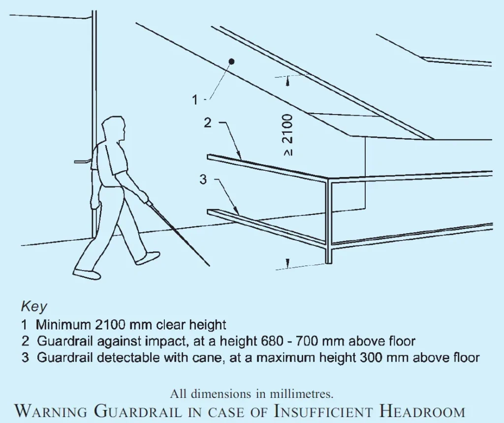
ii) Headroom
- Where headroom is less than 2100 mm from the finished floor level, a warning guardrail or other suitable barrier shall be provided for detection, having its leading edge at or below 680 mm above the finished floor level, such as to enable easy detection with a white cane (see Figure below).
iii) Identification
- Appropriate identification of specific facilities within a building used by the public is particularly essential to the persons with visual impairments.
- Raised letters or numbers shall be used to identify rooms or offices.
- Such identification shall be placed on the wall, to the left of the door, preferably at a height of 1500 mm from the floor and comply with the requirements given in ORIENTATION AND INFORMATION, SIGNAGE, GRAPHICAL SYMBOLS AND VISUAL CONTRAST (please click this link).
iv) Warning Signals
Following requirements with respect to warning signals near barriers shall be complied with:
- Audible warning signals shall be accompanied by simultaneous visual signals for the benefit of those with hearing disabilities.
- Visual signals shall be accompanied by simultaneous audible signals for the benefit of the blind and visually impaired people. To assist blind people, lettering and symbols on signs should be raised for tactile reading.
- Information based on colour codes only should be avoided; colour blind people may find them difficult to understand.
- Signs should be designed, located and illuminated as per ORIENTATION AND INFORMATION, SIGNAGE, GRAPHICAL SYMBOLS AND VISUAL CONTRAST (please click this link).
6) Hazards
- F-a) Where hazards on the direct line of pedestrian travel such as stairs, escalators and moving walks or ramps with a slope of more than 1:16 cannot be avoided, tactile warning indicators and visual markings shall be provided. Every effort shall be exercized to obviate hazards to persons with disabilities.
- F-b) Access panels in walls or manholes in walks, may be extremely hazardous, particularly when in use/open, and shall be avoided. When manholes or access panels are open and in use, or when an open excavation exists on a site, particularly when it is in proximity of normal pedestrian traffic, barricades shall be placed on all open sides, and warning devices shall be installed.
7) Lighting for walkways
Lighting for walkways shall be as given below:
- Lighting should illuminate the walkway; lighting fixtures not exceeding a height of 4 m from ground level should be provided.
- Lighting shall be provided every 20 m to 30m, focusing light not on the car lanes, but on the walkways.
- A white light source, for example high-pressure sodium, is preferable in city and town centres for the aesthetic effect and for better colour definition, which benefits those with poor sight.
- White lighting at average 35 to 40 lux is recommended to ensure colour contrast of tactile blocks and to ensure visibility at night to persons with low vision.
- Light pole may preferably be located within the tree-planting zone.
- Lower-level light poles are preferred to avoid shadow where there are high trees.
By incorporating these considerations into site planning and development, we can create inclusive and accessible spaces that allow persons with disabilities to fully participate in our communities.