If you want to know about the brick masonry or types of bonds in brick masonry or about underpinning, please click the link.
Timbering of trenches and shoring are techniques used in excavation to prevent the collapse of soil and protect workers from harm. Timbering involves installing wooden planks or boards vertically along the walls of a trench, while shoring involves using metal or hydraulic systems to support the trench walls.
Both techniques are important safety measures that should be used when excavating to prevent soil collapse and ensure worker safety.
1) Trench
- Trench is a type of excavation or depression in the ground.
- Trenches are generally defined by being deeper than they are wide (as opposed to a wider gully or ditch), and by being Narrow compared to their length (as opposed to a simple hole).
2) Timbering of Trenches
- When the depth of trench is large, or when the sub-soil is loose, the sides of the trench may cave in.
- The problem can be solved by adopting a suitable method of timbering.
- Timbering of trenches, sometimes also known as shoring consists of providing timber planks or boards and struts to give temporary support to the sides of the trench.
- Timbering of deep trenches can be done with the help of the following methods:
- Stay bracing
- Box sheeting
- Vertical sheeting
- Runner system
- Sheet piling
i) Stay Bracing

- This method is used for supporting the sides or a bench excavated in fairly firm soil, when the depth of excavation does not exceed about 2 meters.
- The method consists of placing vertical sheets called sheathing) or poling boards opposite each other against the two walls of the trench and holding them in position by one or two rows of struts.
- The sheets are placed at an interval of 2 to 4 metres and generally, they extend to the full height of the trench.
- The poling boards may have width of about 200 mm and thickness of 44 to 50 mm. The struts may have size 100 x 100 mm for trench upto 2m wídth and 200 x 200 mm for trench upto 4 m width.
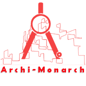
ii) Box Sheeting

- This method is adopted in loose soils, when the depth of excavation does not exceed 4 metres.
- Fig. (a) shows the box like structure, consisting of vertical sheets placed very near to each other (sorne times touching each other) and keeping them in position by longitudinal rows (usuall two) of wales. Struts are then provided across the wales.
- Fig. (b) is adopted for very loose soils in this system, the sheeting is provided longitudinally, and they are supported by vertical wales and horizontal struts. If the height is more, braces are also provided along with struts.
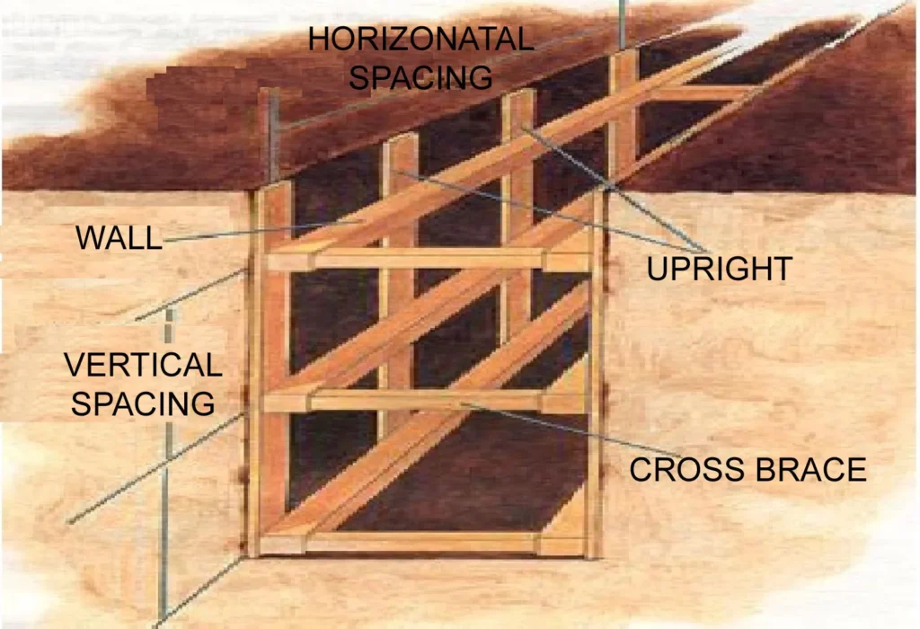
iii) Vertical Sheeting
- This system is adopted for deep trenches (upto 10 m depth) in soft ground.
- The method is similar to the box sheeting, except that the excavation is carried out in stages and at the end of each stage, an offset is provided, so that the width of the trench goes on decreasing as the depth increases.
- Each stage is limited to about 3 m in height and the offset may vary from 25 to 50 cm per stage.
- For each stage, separate vertical sheeting, supported by horizontal wailings and struts are provided.
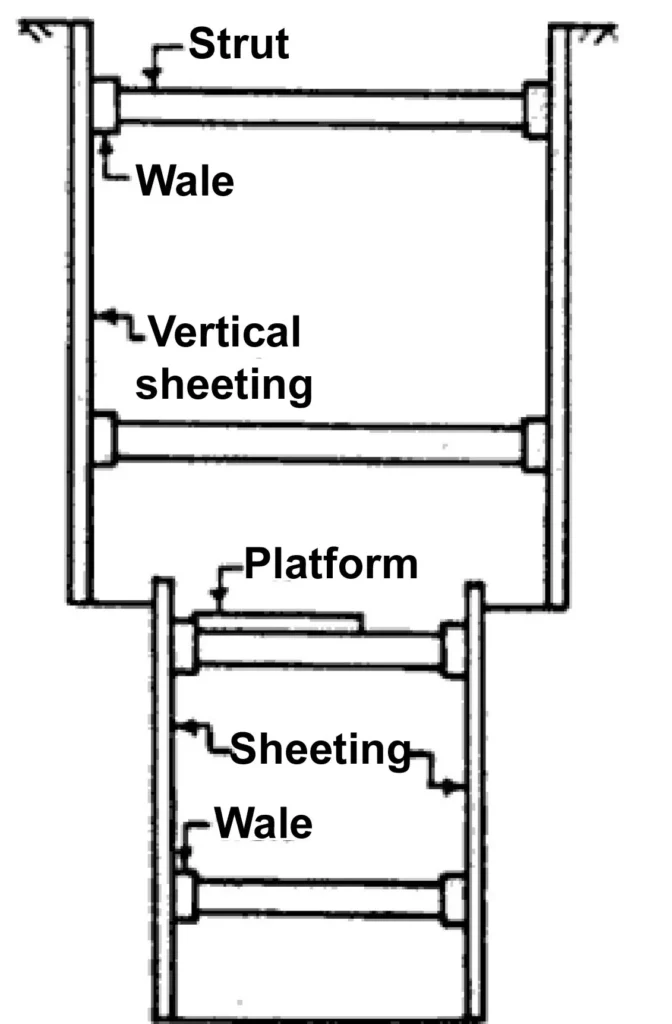
iv) Runner System
- This system is used in extremely loose and soft ground, which needs immediate support as excavation progresses.
- The system is similar to vertical sheeting of box system, except that in the place of vertical sheeting, runners, made of long thick wooden sheets or planks with iron shoe at the ends, are provided.
- Wales and struts are provided as usual. These runners are driven about 30 cm in advance of the progress of the work, by hammering
iv) Sheet Piling
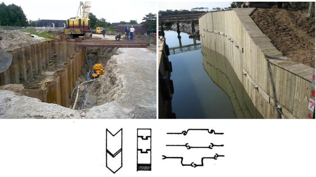
- This method is adopted when
- soil to be excavated is soft or loose
- depth of excavation is large
- width of trench is also large and
- there is sub-soil water.
- Sheet piles are designed to resist lateral earth pressure.
- These are driven in the ground by mechanical means (pile driving equipment). They can be used for excavating to a very large depth.
3) Shoring

Shoring is the construction of a temporary structure to support temporarily an unsafe structure. These support walls laterally. They can be used under the following circumstances:
- When walls bulge out
- When walls crack due to unequal settlement of foundation and repairs are to be carried out to the cracked wall.
- When an adjacent structure needs pulling down.
- When openings are to be newly made or enlarged in a wall.
4) Shoring Types
- Raking shores
- Flying shores
- Dead shores
i) Raking Shores

In this method, inclined members known as rakers are used to give lateral supports to walls. A raking shore consists of the following components.
- Rakers or inclined member
- Wall plate
- Needles
- Cleats
- Bracing
- Sole plate
The following points are to be kept in view for the use of the raking shores:
- Rakers are to be inclined in the ground at. However, the angle may be between 45 degree to 75 degree.
- For tall buildings, the length of the raker can be reduced by introducing rider raker.
- Rakers should be properly braced at intervals.
- The size of the rakers is to be decided on the basis of anticipated thrust from the wall.
- The centre line of a Rakers and the wall should meet at floor level.
- Shoring may be spaced at 3 to 4.5m spacing to cover longer length of the bar.
- The sole plate should be properly embedded into the ground on an inclination and should be of proper section and size.
- Wedges should not be used on sole plates since they are likely to give way under vibrations that are likely to occur.
Note: Raking shore for multistoried Building where inclination of the rakers has to be limited due to short land width available
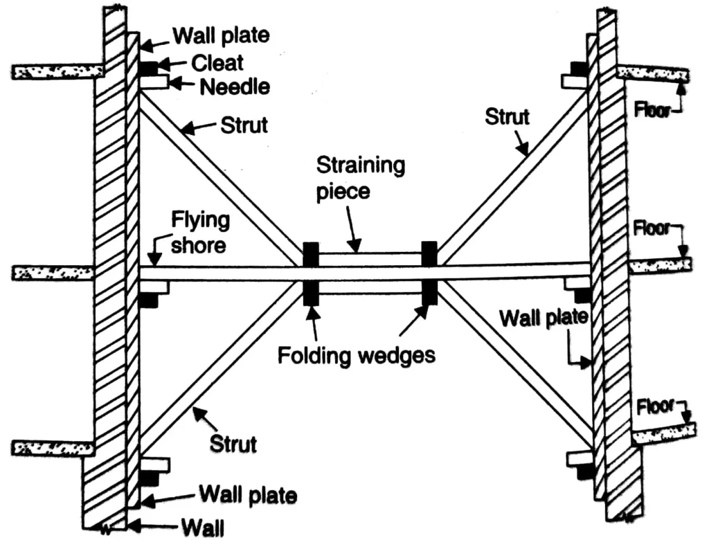
ii) Flying Shores
- It is a system of providing temporary supports to the party walls of the two buildings where the intermediate building is to be pulled down and rebuilt.
- All types of arrangements of supporting the unsafe structure in which the shores do not reach the ground come under this category.
- They flying shore consists of wall plates, needles, cleats, horizontal struts (commonly known as horizontal shores) and inclined struts arranged in different forms which varies with the situation.
- In this system also the wall plates are placed against the wall and secured to it.
- A horizontal strut is placed between the wall plates and is supported by a system of needle and cleats.
- The inclined struts are supported by the needle at their top and by straining pieces at their feet.
- The straining piece is also known as straining sill and is spiked to the horizontal shore. The width of straining piece is the same as that of the strut.
- When the distance between the walls (to be strutted apart) is considerable, a horizontal shore cannot be safe, and a trussed framework of members is necessary to perform the function of flying shore.

iii) Dead Shores
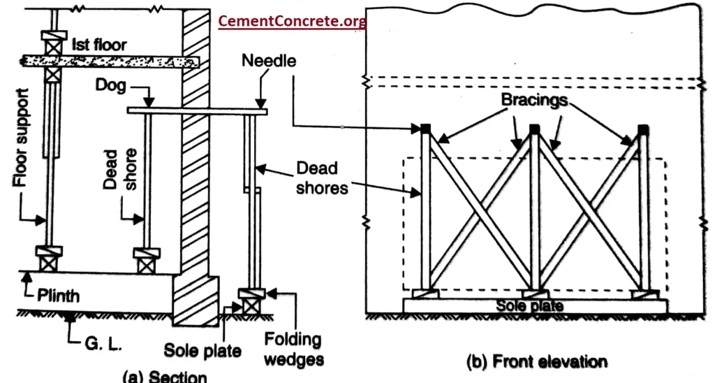
- This is the system of shoring which is used to render vertical support to walls and roofs, floors, etc. when the lower part of a wall has been removed for the purpose of providing an opening in the wall or to rebuild a defective load bearing wall in a structure.
- The dead shore consists of an arrangement of beams and posts which are required to support the weight of the structure above and transfer same to the ground on firm foundation below.
- When opening in the wall are to be made, holes are cut in the wall at such a height as to allow sufficient space for insertion of the beam or girder that will be provided permanently to carry the weight of the structure above.
- Distance at which the holes are cut depends upon the type of masonry and it varies from 1.2m to 1.8m centre.
- Beams called needles are placed in the holes and are supported by vertical props called dead shores at their ends on either side of the wall.
- The needles may be of timber or steel and are of sufficient section to carry the load above.
- The dead shores stand away from wall on either side so as to allow for working space when the needle and the props are in position.
- The props are tightened up by folding wedges provided at their bases while the junction between the prop and the needle is secured with the help of dogs.
- Before the dismantling work is started, all the doors, windows or other openings are well strutted.
- In order to relieve the wall of load of floors and roof above, they are independently supported.
- Vibrations and shocks are bound to occur when wall cutting is done as such a measure of safety raking shores are sometimes erected before commencement of wall cutting operation.
5) Shoring systems consist
- Shoring systems consist of posts, wales, struts and sheeting.
- Three basic types of shoring are:
- Timber
- Hydraulic
- Pneumatic
i) Timber Shoring

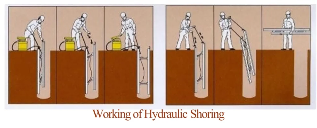
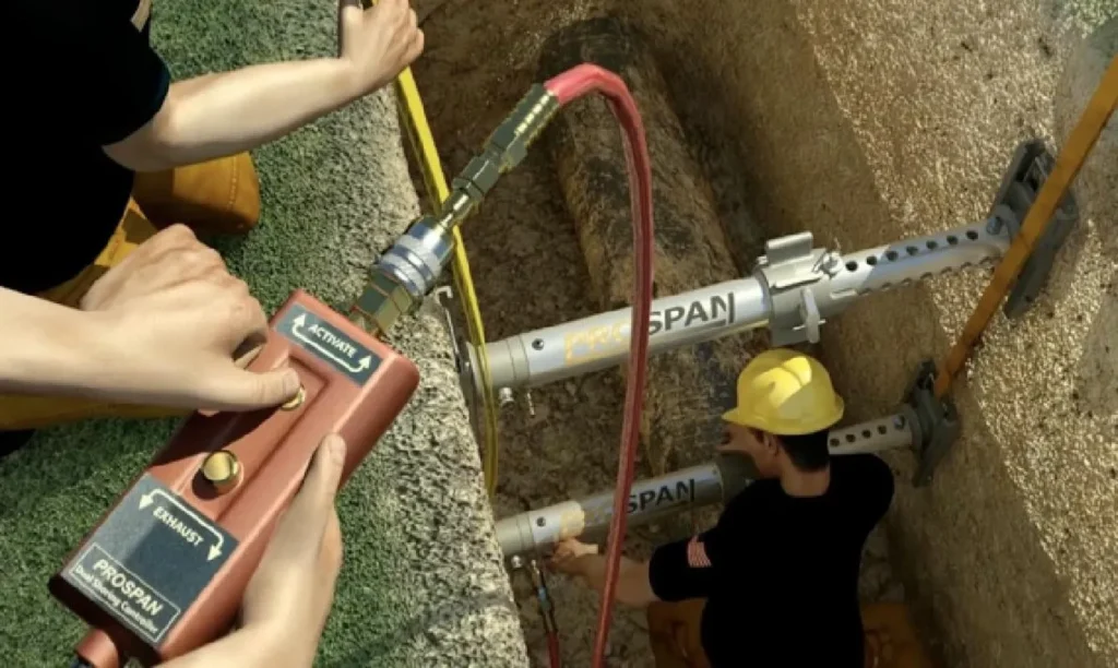
ii) Hydraulic Shoring
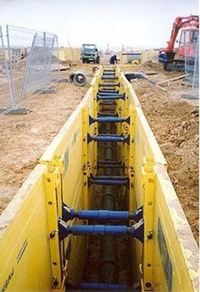
- Hydraulic shoring is the use of hydraulic pistons that can be pumped outward until They press up against the trench walls.
- They are typically combined with steel plate or a special heavy plywood called Finform.
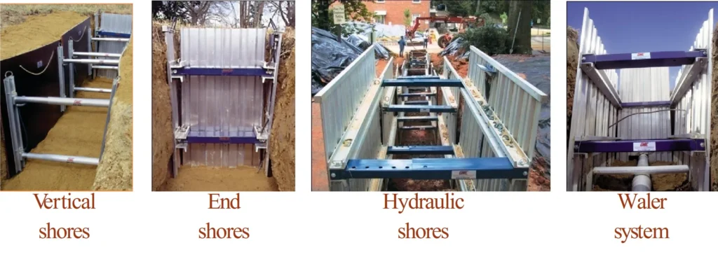
Other Advantages of Hydraulic Systems:
- Easy to install and remove.
- Light enough to be installed by one worker.
- Air gauge – regulated to ensure even distribution of pressure along the trench line.
- Can be adapted easily to various trench depths and widths.

iii) Pneumatic Shoring
- It uses air pressure.
- Anti Projectile feature
- Tethered pin
- Cast aluminum Handles
- Manual Lock
- Anodized Aluminum
- Air inlet fitting
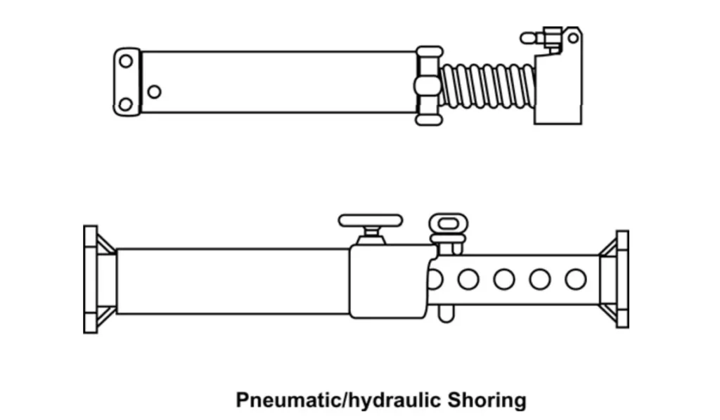
- Note: Its length varies from 21” to 105”. Comes in various models according to its need.
Overall, proper trenching and shoring techniques are essential to protect workers and prevent accidents in excavation work.
sir, when concrete is to be placed in the excavated trench, how to remove the shoring wooden planks are removed or they have to be left in concrete??
The materials are relevant
nice one
I really appreciate
Its really helpful to us students
Really amazing and helpful
It really explains things well
Engineers must visit this site and read about it