
If you want to know about the water supply requirements for building or rainwater harvesting system or principles of water supply, please click the link.
A water supply system in a tall building typically involves the use of pumps to deliver water to upper floors. The system is designed to ensure that there is adequate water pressure and flow rate throughout the building, even at higher elevations.
The system generally consists of a water storage tank located at the top of the building or on the roof. This tank is filled with water from a municipal water supply or from a well or other water source. The tank typically has a capacity that is sufficient to provide water to the building for a certain amount of time, even if the municipal water supply is interrupted.
1) Introduction
In General
- In skyscrapers (Multi-Storeyed Buildings or tall building) Plumbing is one of the more challenging problems to solve due to the loss in pressure as water travels up a vertical pipe.
- As the building get taller, another problem arises as the water pressure at the bottom of a vertical pipe becomes too great for safe operation and building codes.
The Solution
- The early solution to this problem was a water tank mounted on the top of a building with fill pumps at the bottom of the building, a simple gravity down feed arrangement.
- Today, a system of pressure-reducing valves and sub-risers are used to manage the inconsistent water pressure throughout a skyscraper (Tall building).
- Pressure-reducing valves reduce the pressure at the bottom of the building, while sub-risers increase the pressure for the skyscrapers upper floors.
2) System of supply
i) Direct supply system
- Supply of water given directly to various floors of the buildings from the mains having sufficient pressure for the sufficient number of hours pressure at fixture is more than required. Recommended only if number of floors are not more 2 to 5.
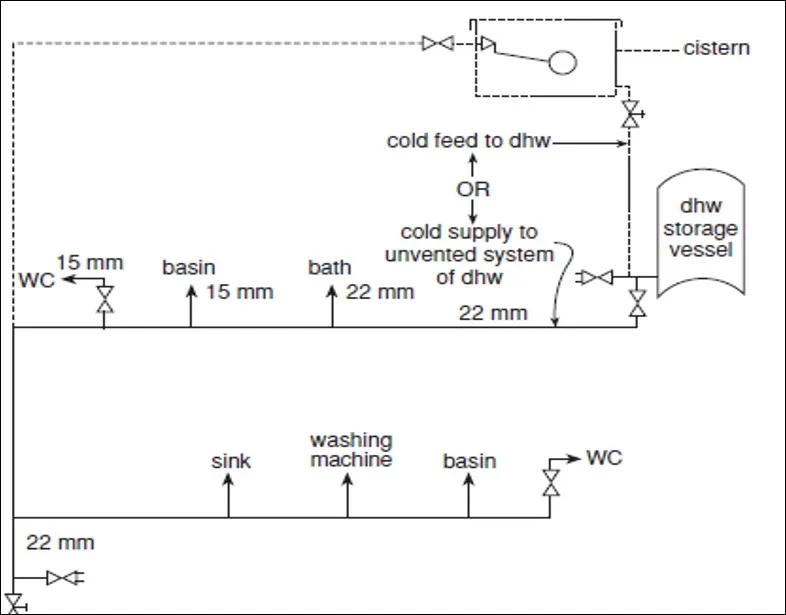
ii) Indirect supply system
- When water pressure in mains is not sufficient for direct supply water from mains can be either pumped up into the over storage tank, usually situated at the roof of the building from where the water is supplied to different floors by gravity or stored into the underground storage tank from where water is pump to the OHT. & than it is supplied by gravity.
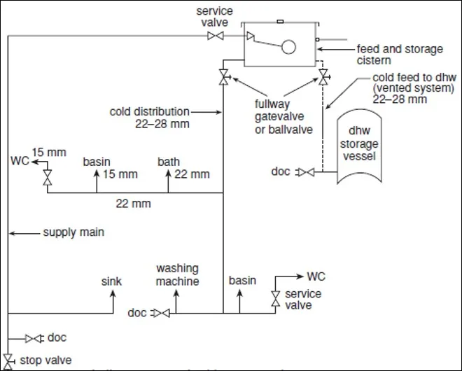
In very tall buildings it is advantageous to use separate drinking and water ground, intermediate and roof level cisterns.
The separate drinking and cold-water cisterns spread the load of water storage up the building and limit pressure in the distributing both to drinking outlets and sanitary appliances.
3) Distribution systems
There are following four basic methods of distribution of water to a multistoried building (Tall buildings).
- Direct supply system from mains – public or private.
- Gravity distribution system.
- Pressurized distribution system (Hydro-pneumatic pumping system).
- Combined distribution system.
i) Direct supply system from mains – public or private
- This system is adopted when adequate pressure is available in the mains to supply water at adequate pressure at the topmost floor.
- With limited pressure available in most city mains, water from direct supply is normally not available above two or three floors.
- Useful when pressure is available round the clock at the topmost floor.
- The pressure may not be available so generally floors above 2nd or 3rd storey face short fall of water pressure.
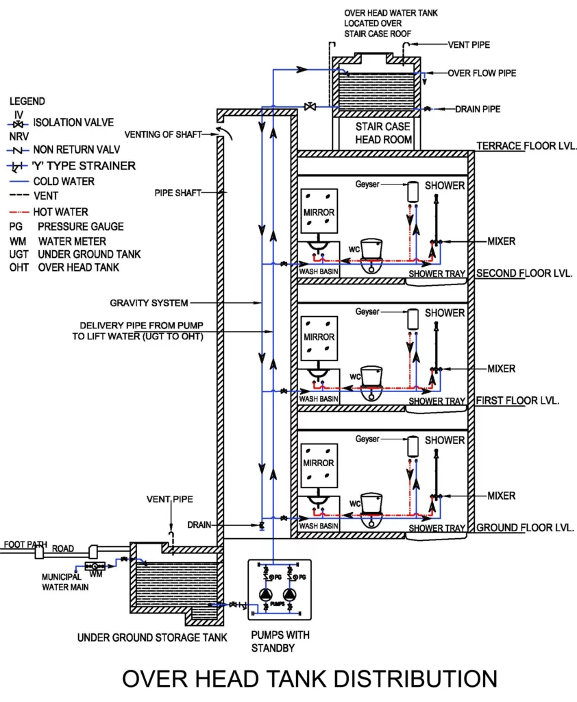
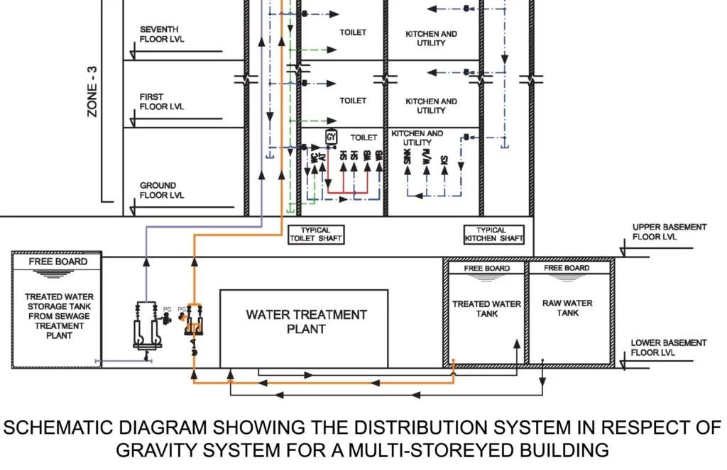
ii) Gravity distribution system
- This is the most common water distribution system.
- The system comprises pumping water to one or more overhead water tanks.
- Water transferred to overhead tank(s) is distributed by gravity to various parts of the building by the system of piping network.
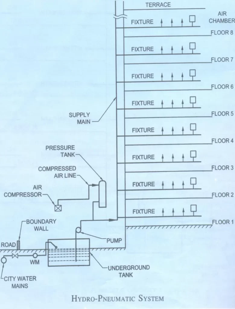
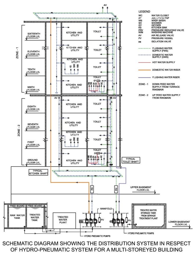
iii) Pressurized Distribution System (Hydro-pneumatic Pumping System)
- Variation of direct pumping system.
- Air tight pressure vessel is installed on line to regulate the operation of the pumps.
- The pressure switch installed in the pressure vessel/tank switches off after reaching the predetermined pressure and the operating pump is put to stop.
- Air compressor is necessary to feed the water with air to maintain the air water ratio.
- This system eliminates the need of an OHT and supplies water at a much higher pressure resulting in even distribution of water on all floors
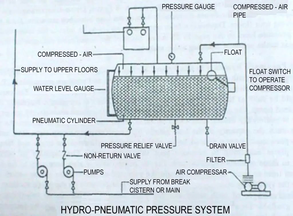
- Pressurized distribution system is a direct pumping system incorporating a recharge diaphragm vessel.
- The system may incorporate multiple pumps with suction and discharge manifolds and a control panel to facilitate automatic operation.
- Total discharge capacity required may be shared by a number of pumps, where the pumps operate in duty, assist and standby configuration.
- The system shall also incorporate automatic sequencing of pumps to ensure even wear and tear also a low-level cutoff, to prevent dry run of the pumps.
- The system shall be provided with continuous power supply with provision of emergency power backup.
- Modern hydro-pneumatic systems are available with variable frequency drive, where the pump is efficiently used to deliver water at rates of flow as required by the system, by varying its speed with the assistance of an electronic device, thereby meeting the demand flow through variation in speed of the motor from 960 rpm to 3 000 rpm. With this arrangement, the same pump is able to deliver water at required pressure and flow as required at different times of the day.
- The system consumes energy in proportion to the work done and also helps in controlling the water surge in the distribution line.
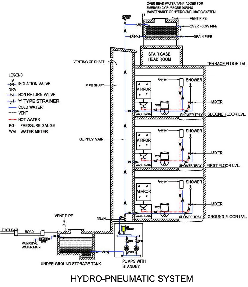
- Hydro-pneumatic system generally eliminates the need of an overhead tank.
As a good engineering practice and to take care of emergencies, an overhead of smaller capacity should be provided which feeds by gravity to the system as shown in figure below.
Note
- Hot water supply to be planned as per requirement by provision of geyser and hot water piping.
- Flushing water supply from WC to be planned in case availability of recycled waste water.
- For large and commercial buildings, water supply to be based on zone-based distribution for domestic and flushing water supply.
- Presentation of layout and location of fixtures/appliances are only typical in nature.
iv) Combined Distribution System
- In this system, a combination of gravity and pressurized distribution is adopted. A few upper floors are provided with a pressure booster pumping system to achieve the desired residual pressure, while the lower floors are fed by gravity supply.
- Water collected in the overhead tank is distributed to the various parts of the building. To achieve required residual pressure for top 2 to 4 floors for proper functioning of the fixtures, a pressure booster pumping system is installed on the dedicated outlet from overhead tank with its own distribution piping serving the top 2 to 4 floors. For lower floors, water is distributed by gravity system.
- Water distribution is accomplished by providing down take pipes in the shaft from the terrace ring mains. See figure below

Note
- Pump operation to be by level controller or air vessel/pressure switch at motorized valve at OHT.
- Hot water supply to be planned as per requirement by provision of geyser and hot water piping.
- Flushing water supply from WC to planned in case of availability of recycled waste water.
- For large and commercial buildings, water supply to be based on zone-based distribution for domestic and flushing water supply.
- Presentation of layout and location of fixtures/appliances are only typical in nature.
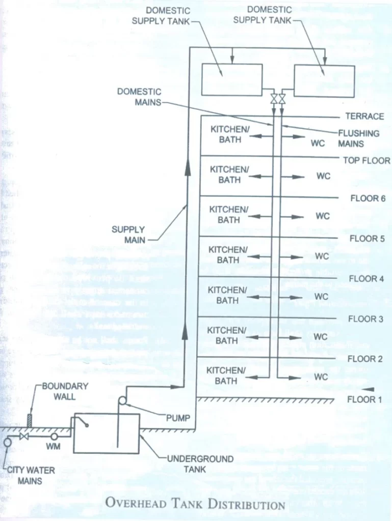
4) Zoning of Distribution Systems
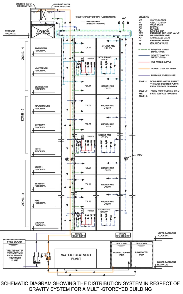
- The zoning of water distribution network may be adopted for 7 to 9 floors, while conforming to the adequate pressure requirements and excessive pressure limitations in the hydraulic design. See Figure below for zoning of gravity distribution system and pressurized distribution system (hydro-pneumatic pumping system), respectively.
- The recommended maximum permissible velocity is 2.4 m/s for water distribution. In case of hot water distribution through copper pipes, the velocity is restricted to 1.5 m/s due to concern of erosion of the piping material.
i) Gravity distribution system for tall building

Note
- Appurtenance, such as PRV should be planned in main piping network or branch piping, as required, to restrain pressure to upper limits.
- Requirements for storage and usage of fire water shall be as per Fire Safety Rules.
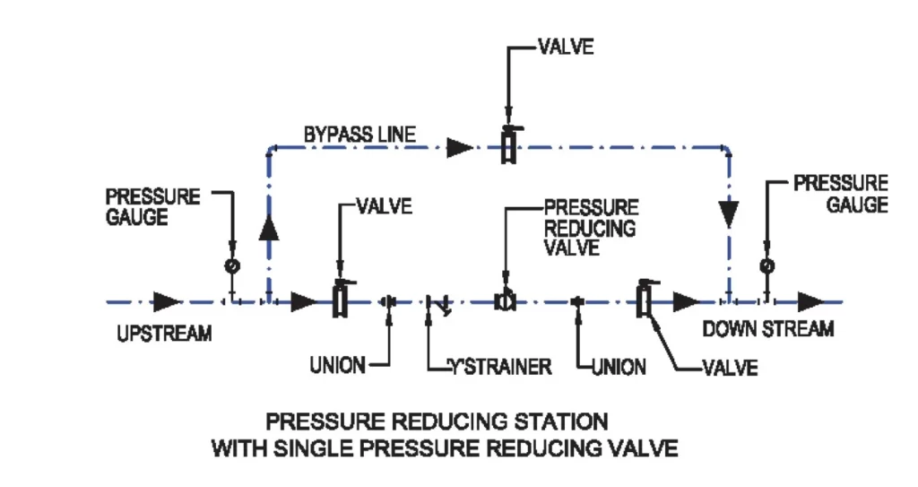
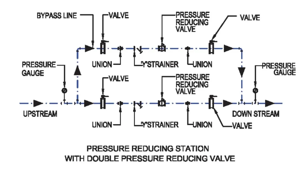
Pressure reduction station for both System
ii) Pressurized distribution system (hydro-pneumatic pumping system) for tall building
Note
- The given example is for 16 storeyed building with concept of upfeed and down feed ringmains. The choice of ringmain is on designer proposal. For taller building, zones and ringmains shall be planned to meet maximum and minimum pressure requirements. Appurtenance, such as PRV should be planned in main piping network or branch piping, as required, to restrain pressure to upper limits.
- Requirements for storage and usage for fire water shall be as per Fire Safety Rules.
5) Quantity of water
The quantity of water to be stored shall be calculated taking into account the following factors:
- Hours of supply at sufficiently high pressure to fill up the overhead storage tanks.
- Frequency of replenishment of overhead tanks, during the 24 hrs.
- Rate and regularity of supply.
Consequences of exhausting storage particularly in case of commercial buildings.
- Pressure-reducing valves are introduced on lower floors for more than 30 to 35mts. Head of water to reduced the water pressure.
- Separate lines are used for every 4 or 5 floors. If the same line is used for entire building then the upper floor occupants will find it difficult to get adequate quantity of water when the lower floor occupants open the taps.
6) Storage of water
Reason for storage of water
- To provide water against interruption of the supply caused by repair to mains, etc.
- To reduce the maximum rate of demand on the mains.
- To maintain a storage for the fire fighting requirement of the bldg.
Material used
- Reservoir and tanks shall be constructed of reinforced concrete, cast iron, wrought iron or galvanized mild steel plate or sheets.
- If the storage capacity required is more than 5000 ltr it is advantageous to arrange it in a series of tanks so interconnected, that each tank can be isolated for cleaning and inspection without interfering with the supply of water.
Overall, designing and implementing an effective water supply system in a tall building requires careful planning, engineering, and ongoing maintenance to ensure that the system is reliable and can provide safe, clean water to occupants of the building.
Great knowledge
HI, I FOUND THIS ARTICLE AND OTHER USEFUL FOR ME BUT COULD NOT DOWNLOAD IT. CAN YOU HELP WITH IT PLEASE.
fire protection system
EXCELLENT WORK DONE
Pls want the pdf of this notes
Excellent information. I appreciate this a lot.
I am trying to understand better on how to decide between a combined system and a fully pressurized system. If anyone has any advice I would appreciate it.