
If you want to know about the cluster planning for housing or proportion in architecture or arrangements for various plumbing fixtures, please click the link.
- Manholes are used for connecting two or more converging storm or sanitary sewers, permitting pipe size changes, accommodating abrupt changes in alignment or grade and allowing for direct surface flow interception.
- A manhole or inspection chamber shall be capable of sustaining the loads which may be imposed on it, exclude subsoil water and be water tight.
- The size of the chamber should be sufficient to permit ready access to the drain or sewer for inspection, cleaning and rodding and should have a removable cover of adequate strength, constructed of suitable and durable material.
- Where the depth of the chamber so requires, access rungs, step irons, ladders or other means should be provided to ensure safe access to the level of the drain or sewer.
- If the chamber contains an open channel, benching should be provided having a smooth finish and formed so as to allow the foul matter to flow towards the pipe and also ensure a safe foothold.
- No manhole or inspection chamber shall be permitted inside a building or in any passage therein.
- The minimum depth of the manhole shall not be less than 800 mm to facilitate gully trap connection. Further, ventilating covers shall not be used for domestic drains.
- At every change of alignment, gradient or diameter of a drain, there shall be a manhole or inspection chamber. Bends and junctions in the drains shall be grouped together in manholes as far as possible.
- Alternative materials of manholes using RCC rings and PVC in sewer lines are being used in some sites. These may be considered subject to ensuring their proper design, keeping in view the lateral and vertical loads at the place of installation.
1) Spacing of manholes
The spacing of manholes for a given pipe size should be as follows:
| Sr. No. | Pipe Diameter (mm.) | Spacing of Manhole (m.) |
| 1) | Up to 300 | 45 |
| 2) | 301 to 500 | 75 |
| 3) | 501 to 900 | 90 |
| 4) | Beyond 900 | Spacing shall depend upon local condition and shall be gotten approved by the Authority |
- Where the diameter of a drain is increased, the crown of the pipes shall be fixed at the same level and the necessary slope given in the invert of the manhole chamber.
- In exceptional cases and where unavoidable, the crown of the branch sewer may be fixed at a lower level, but in such cases the peak flow level of the two sewers shall be kept the same.
2) Size of manhole
- The manhole or chamber shall be of such size as will allow necessary examination or clearance of drains. The size of shall be adjusted to take into account any increase in the number of entries into the chamber.
- Manholes may be rectangular, arch or circular type.
- The minimum internal size of manholes, chambers (between faces of masonry) shall be as follows:
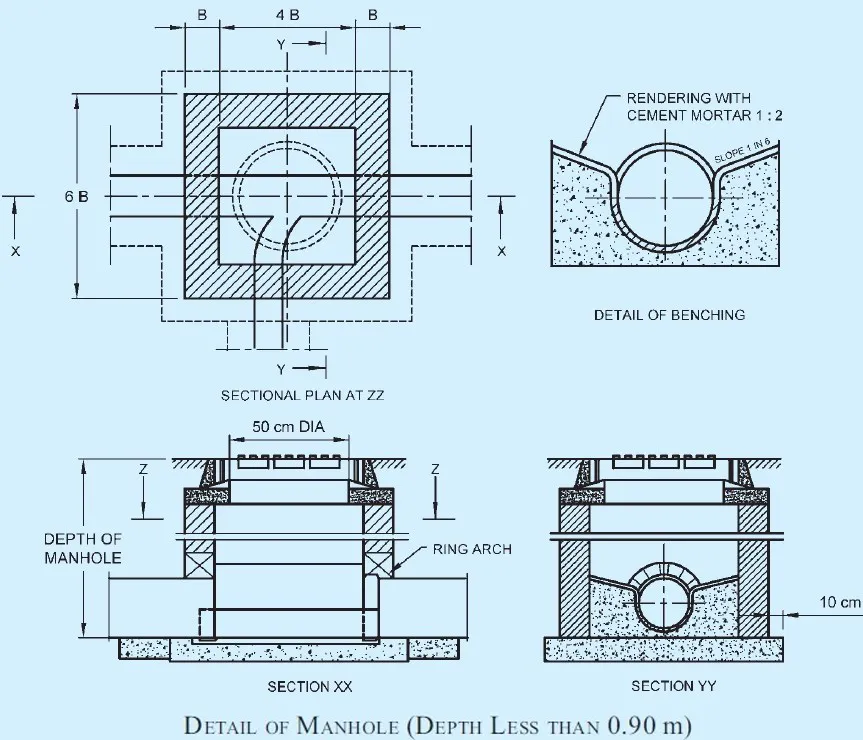
i) Rectangular manholes
- For depths less than 0.90 m. = 900 mm x 800 mm.
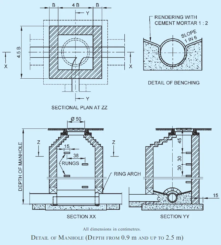
- For depths from 0.90 m and up to 2.5 m. = 1200 mm x 900 mm.
Note – For depths upto 0.60 m, 600 mm × 600 mm manhole may be used.
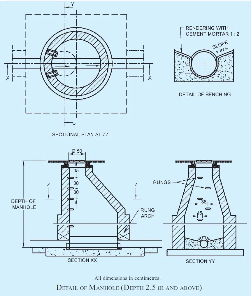
ii) Arch type manholes
- For depths of 2.5 m and above = 1400 mm x 900 mm.
Note – The width of manhole chamber shall be suitably increased more than 900 mm on bends, junctions or pipes with diameter greater than 450 mm so that benching width in either side of channel is minimum 200 mm.
iii) Circular manholes
- For depths above 0.90 m and up to 1.65 m = 900 mm (diameter)
- For depths above 1.65 m and up to 2.30 m = 1200 mm (diameter)
- For depths above 2.30 m and up to 9.00 m = 1500 mm (diameter)
- For depths above 9.00 m and up to 14.00 m = 1800 mm (diameter)
Notes
- In adopting the above sizes of chambers, it should be ensured that these sizes accord with full or half bricks with standard thickness of mortar joints so as to avoid wasteful cutting of bricks.
- The sizes of the chambers/manhole may be adjusted to suit the availability of local building materials, economics of construction and to meet local authority approval.
- The access shaft shall be corbelled inwards on three sides at the top to reduce its size to that of the cover frame to be fitted or alternatively the access shaft shall be covered over by a reinforced concrete slab of suitable dimensions with an opening for manhole cover and frame.
- The minimum sewer pipe diameter is 200 mm based on good practice.
3) Construction of manholes
i) Excavation
- The manhole shall be excavated true to dimensions and levels as shown on the plan.
- The excavation of deep manholes shall be accompanied with safety measures like timbering, staging, etc.
- In areas where necessary, appropriate measures for dewatering should be made.
ii) Bed concrete
- The manhole shall be built on a bed of concrete 1:4:8 (1 cement : 4 coarse sand : 8 graded stone aggregate 40 mm nominal size).
- The thickness of bed concrete shall be at least 150 mm for manholes up to 0.9 m in depth, at least 200 mm for manholes from 0.90 m up to 2.5 m in depth and at least 300 mm for manholes of greater depth, unless the structural design demands higher thickness.
- This thickness may be verified considering the weight of wall, cover, the wheel loads, impact of traffic which are transmitted through cover and the shaft walls and for water pressure, if any.
- In case of weak soil, special foundation as suitable shall be provided.
iii) Brickwork
- The thickness of walls shall be designed depending upon its shape and taking onto account all loads coming over it, including earth pressure and water pressure.
- Generally, the brickwork shall be with first class bricks in cement mortar 1: 5 (1 cement : 5 coarse sand).
- All brickwork in manhole chambers and shafts shall be carefully built in English Bond, the jointing faces of each brick being well ‘buttered’ with cement mortar before laying, so as to ensure a full joint.
- The construction of walls in brickwork shall be done in accordance with good practice.
For various depths the recommended thickness of wall may be as follows:
- Depth of the chamber thickness of wall
- Up to 2.25 m : 200 mm (one brick length)
- From 2.25 m up to 3.0 m : 300 mm (one and half brick length)
- From 3.00 m up to 5.0 m : 400 mm (two brick length)
- From 5.00 m up to 9.0 m : 500 mm (two and half brick length)
- Above 9.00 m : 600 mm (three brick length)
- The actual thickness in any case shall be calculated on the basis of engineering design.
- Typical sections of the manholes are illustrated in Figures Below.
Notes
- Rich mix of cement mortar, not weaker than 1:3, should be used in brick masonry, where subsoil water conditions are encountered.
- For arched type of manholes, the brick masonry in arches and arching over pipes shall be in cement mortar 1:3.
iv) Plastering
- The wall shall be plastered (15 mm, minimum) both inside and outside within cement mortar 1:3 and finished smooth with a coat of neat cement.
- Where subsoil water conditions exit, a richer mix may be used, and it shall further be waterproofed with addition of approved waterproofing compound in a quantity as per manufacturer specifications.
- All manholes shall be so constructed as to be water- tight under test.
- All angles shall be rounded to 75 mm radius, and all rendered internal surface shall have hard impervious finish obtained using a steel trowel.
v) Channels and benching
- These shall be semi-circular in the bottom half and of diameter equal to that of the sewer.
- Above the horizontal diameter, the sides shall be extended vertically 50 mm above the crown of sewer pipe and the top edge shall be suitably rounded off.
- The branch channels shall also be similarly constructed with respect to the benching, but at their junction with the main channel an appropriate fall, if required suitably rounded off in the direction of flow in the main channel shall be given.
- The channel/drain and benching at the bottom of the chamber shall be done in cement concrete 1:2:4 and subsequently plastered with cement mortar of 1:2 proportion or weaker cement mortar with a suitable waterproofing compound and finished smooth, to the grade (where required).
- The benching at the sides shall be carried up in such a manner as to provide no lodgment for any splashing in case of accidental flooding of the chamber.
- Channels shall be rendered smooth and benchings shall have slopes towards the channel.
vi) Rungs
- Rungs shall be provided in all manholes over 0.8 m in depth and shall be of cast iron, or PVC encapsulated or composite non-corrosive materials, and of suitable dimensions, conforming to accepted standards.
- These rungs may be set staggered in two vertical rungs which may be 300 mm apart horizontally as well as vertically and shall project a minimum of 100 mm beyond the finished surface if the manhole wall.
- The top rung shall be 450 mm below the manhole cover and the lowest not more than 300 mm above the benching.
vii) Manhole covers and frames
- The size of manhole covers shall be such that there shall be a clear opening of at least 500 mm in diameter for manholes exceeding 0.90 m in depth.
- The manhole covers and frames used shall conform to accepted standards.
- The frame of manhole shall be firmly embedded to concrete alignment and level in plain concrete on the top of masonry.
viii) Drop manhole
- Where it is uneconomic or impracticable to arrange the connection within 600 mm height above the invert of the manholes, the connection shall be made by constructing a vertical shaft outside the manhole chamber, as shown in Figure.
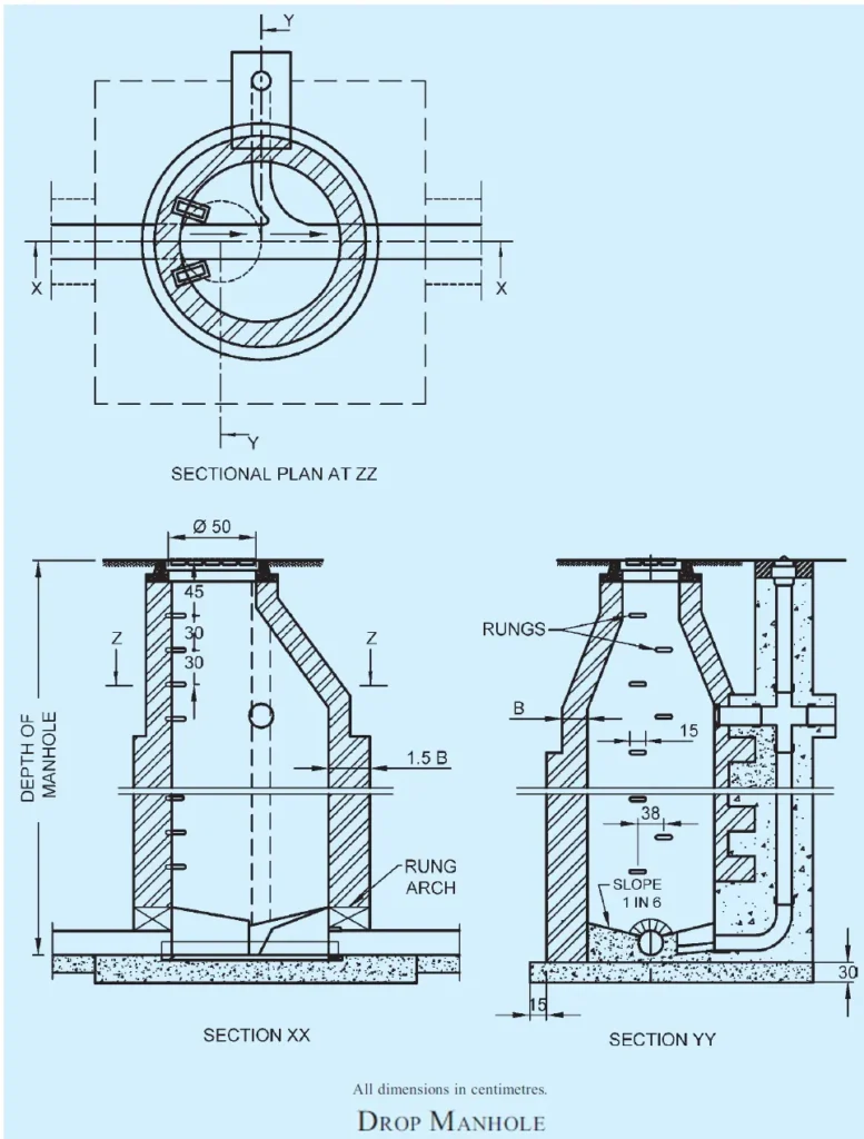
Note – Wall thickness have been indicated in brick length to provide for use of modular bricks or traditional bricks.
In the figure, B = one brick length, 1.5 B = one and a half brick length, etc.
- If the difference in level between the incoming drain and the sewer does not exceed 600 mm, and there is sufficient room in the manhole, the connecting pipe may be directly brought through the manhole wall and the fall accommodated by constructing a ramp in the benching of the manhole.
ix) Manhole covers and recommended locations
- Manhole covers were traditionally and presently manufactured from concrete, steel fibre reinforced concrete, cast iron and ductile iron or PVC materials and these materials are used based on the load carrying capacity and for the following type of applications:
- Inspection chambers for sewerage.
- Underground electrical cabling.
- Telecom cabling.
- Water, gas and petroleum installations; and
- Beautification of gardens and landscapes.
- Recommended locations conforming to load capacity shall be as per accepted standard.
Can we construct ugd manholes using solid cement bricks.Sqare or round manhole which is best pl.let meknow