If you want to know about the water supply requirements for buildings or rainwater harvesting system or types of floor finishes, please click the link.
Sewerage systems in tall buildings are a critical part of the building’s plumbing infrastructure. A well-designed sewerage system is necessary to ensure that wastewater is effectively collected, transported, and disposed of from high-rise buildings.
- The fundamental purpose of a high-rise system is that the removal of fluid and solid waste to the sewer, while protecting the inhabitants of the building form cross contamination from sewer gases and pathogens from within the system, by ensuring water trap seals are maintained.

1) Waste disposal system
- Collection treatment and disposal of inorganic waste, like traditional methods, garbage chutes, urban solid waste treatment systems, composting etc.
- Solid waste can be divided into three section.
- Collection of solid waste,
- Conveyance of solid waste,
- Disposal of solid waste
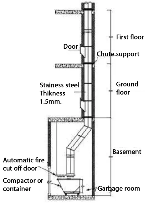
Refuse (Garbage) chutes conveyance within multi-stored buildings
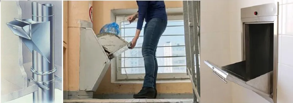
- Refuse chute systems built in multistoreyed residential buildings for transporting and collecting the refuse from flats at different heights.
- The refuse is received form the successive flats through the located on the vertical system of pipes that convey refuse through it and discharge into the collecting chamber from where the refuse is cleared at suitable intervals.
- Components of garbage chute are the inlet hopper (flap opening), the collection chamber (wheel container) is placed in a placed in chamber of waste for periodic removal) and vent at top.
Main components
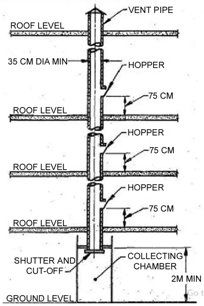
- Chute – A vertical pipe system passing from floor to floor provided with ventilation and inlet openings, for receiving refuse from successive flats and handing at the ground floor on the top of the the collecting chamber.
- Intel Hopper – A receptacle fitting for receiving refuse from each flat and dropping it into the chute. Inlet Hopper shall be located 750 mm. above floor level – for ground floor flats the inlet hopper may be placed at a higher level and a flight of steps may be provided for using same.
Design and construction
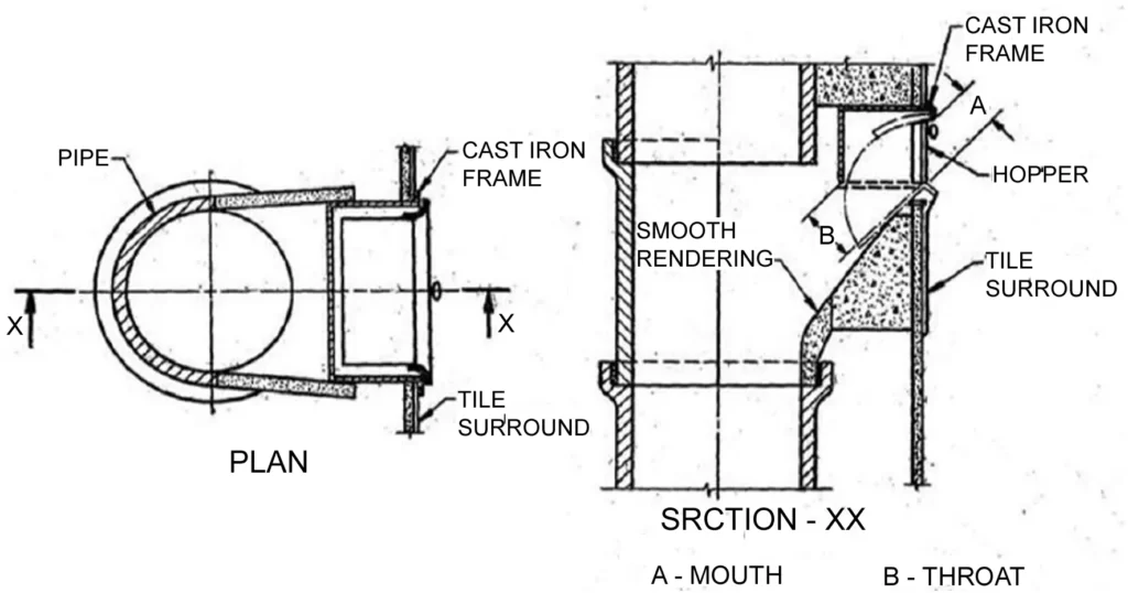
- Hopper should be constructed such that there should be minimum escape of odour or any other vapour when the hopper door is kept open – The hopper flap shall not open inside the chute pipe. which might obstructs refuse coming from the top.
- The door and frame should be fire resistant.
- The door and mouth and throat – the mouth shall have a maximum size od 25 cm height and 36 cm width. The throat should not be less than the size of mouth. The diagonal of mouth should not be larger than the chute size.
- Height of hopper — the hopper should be constructed at height of 75cm measured from the floor level to the lower edge of the inlet opening.
- Inner surface – The interior of the hopper should slope towards the main chute at angle not less than 45 to 60 degree to the horizontal for better performance. The inside finish should be as smooth as possible
- Collection Chamber – A compartment suited at the lower end of the chute for collecting and housing the refuse during the period between two successive clearing.
- It may be recommended to provided to provide a minimum capacity of 0.054 m3/family or apartment per day.
- In the case of chutes serving small number of apartments, the minimum size of the collecting chamber shall be 1.2 x 1.2 x 1.8 m. in order to providing trolley and easy cleaning of the chamber.
- Normally the height of chute bottom above the top of container shall be about 30 cm in order not to allow any refuse to spill on the floor of the chamber.
- It will be preferable a minimum head room of 2 m for the collection chamber to facilities easy entry into it
Collection & estimation of wastewater
Different types of sewers:
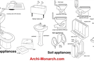
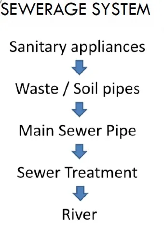
- Soil pipe:- It is pipe carrying sewage from latrine in a house drainage system, It is one of the composition a house drainage system.
- Waste pipe – It is pipe carrying wastewater from bathroom sinks and kitchen, it is one of the components of house drainage system.
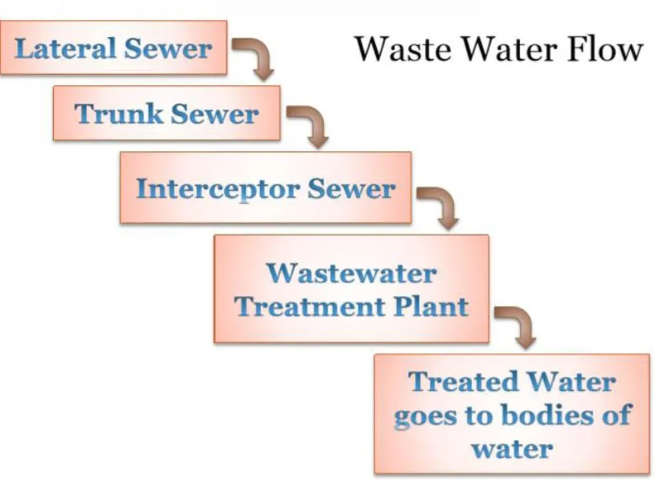
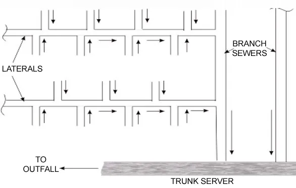
- Lateral sewer – it is sewer receiving domestic wastewater from house sewer. It is one of components of sewerage system of town or city.
- House sewer – in house drainage system the domestic wastewater of a house is carried by house sewer to municipal sewer called lateral. House sewer is one of the component of house drainage system.
- Branch sewer – the sewer which receives water from laterals sewers is called as branch sewer. It is one of the component of sewerage system of city or town.
- Main sewer – a main sewer is the sewer which receives wastewater from the branch sewers. It is one of the component of sewerage system of city or town.
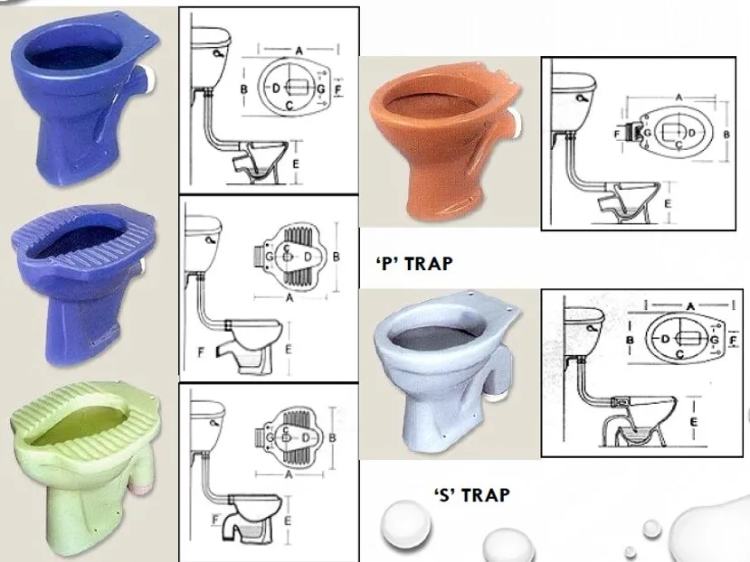
Types of traps
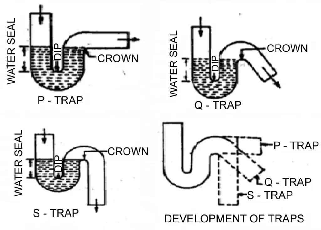
According to shape
- “P” Trap
- “Q” Trap
- “S” Trap
According to use
- Floor Trap
- Gully Trap
- Intercepting Traps
- Grease Traps
Traps Examples
2) Drainage system
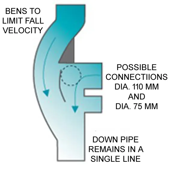
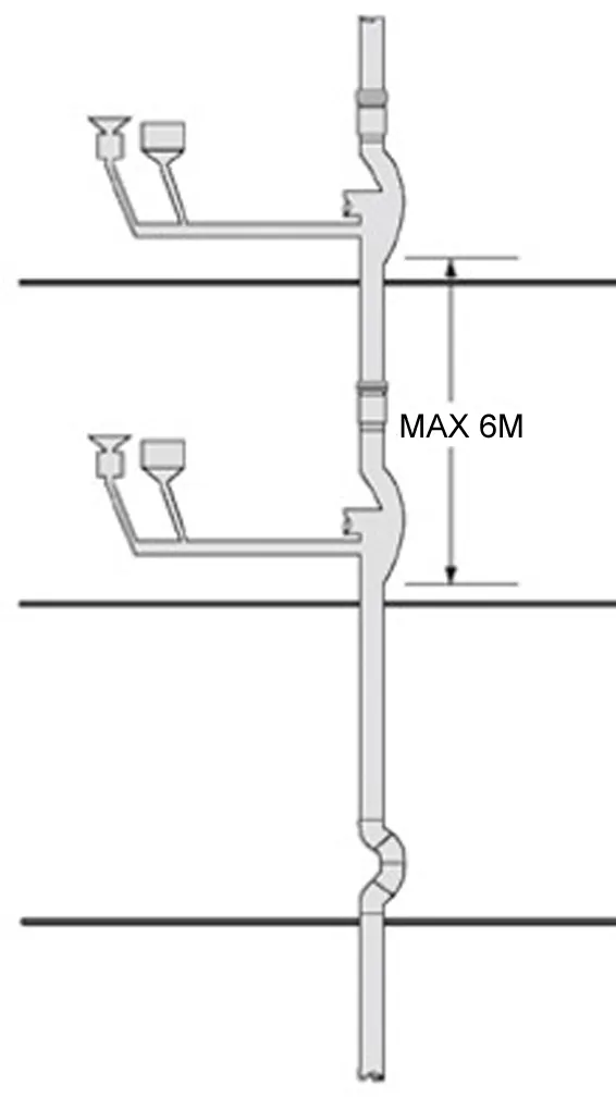
- Drainage is another common issue in skyscrapers and is often just as difficult to solve as water pressure problems.
- Once the gravity propelled water hits a horizontal bend in the pipe, the flow velocity drops dramatically, and fills the pipe considerably more due to the lost speed.
- It is common practice to use relief or yoke vents to slow the water before it encounters a horizontal flow change.
- The piping at the base of a vertical drainage column must be secured, as to reduce the risk of breaking joints.
Drainage in multistoried developments
- One pipe system
- Dual pipe system
- Fully ventilated stack system
- Single stack system
- Modified single pipe system
One pipe system

- In a system all soil and waste discharge into one common pipe and branch ventilating pipes into one main ventilating pipe.
- This is system largely replaces the two pipe system and lent itself very well to use in multi-story developments.
- It is far more economical than two pipe system
- If this system is provided in multi-storey building the lavatory blocks of various floors are so placed one over the other so that the wastewater discharge from the different units can be carried through short branch drain.
- The main pipe is directly connected to the drainage system
Two pipe system
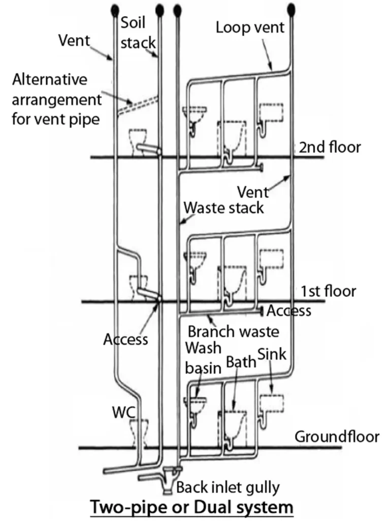
- The waste stack received the discharge ablutionary fitments and conveyed this to the ground level where it was delivered above the water seal in a trapped gully connected to the drainage system.
- The soil stack recieves the discharge from soil appliance and delivered it directly to the undergoing system.
- The waste and soil water did not combine until they reached the below ground drainage system.
- Two sets of pipes are laid. the soil fixtures such as urinals and water closets are connected to vertical soil pipe.
- The connections o waste matter from baths, kitchens etc are made to another vertical waste pipe.
- The soil pipe and the waste pipe are provided with separate vent pipes.
- It will thus require four pipes and hence it becomes costly. the number of pipes on walls face is also more and if not properly maintained these pipes form nuisance.
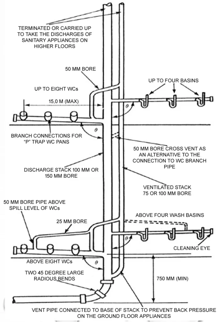
The fully ventilated one-pipe system
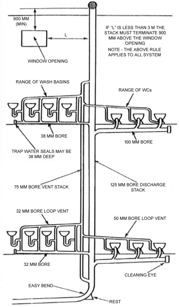
- A large number of sanitary appliances in ranges.
- Each trap with an anti—siphon or vent pipe connected to the discharge pipe in direction of flow of water at a point between 75-450 mm. from trap crown.
- Vent stack connected to the discharge stack near to the bend ti remove compressed air at this point
The single stack system
- Reduce the cost of soil and waste systems.
- Branch vent pipes are not required.
- To prevent loss of trap water seals.
- The trap water seal on the waste traps must be 76 mm. deep.
- The slopes of branch pipes are: sink and bath, 18 to 19 mm. /m., basin 20-120 mm. /m., WC 18 mm. /m. (min).
- Vertical stack at 200 mm. below the centre to the WC Branch connection.
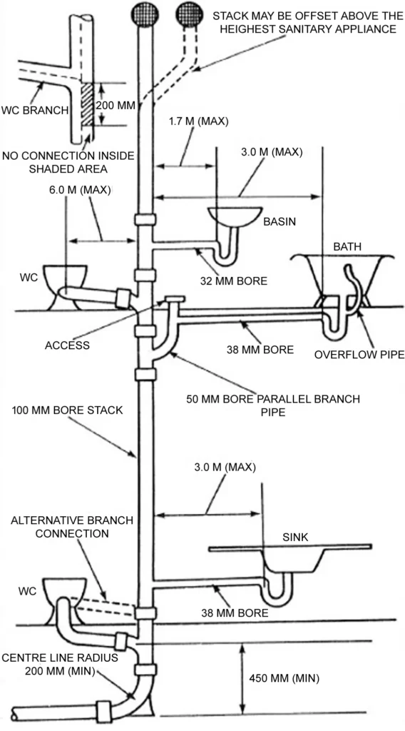
Modified single stack system
- Close grouping of sanitary appliances -> install the branch waste and soil pipes without the need for individual branch ventilating pipes.
- To prevent the loss of trap water seals —> WC branch pipe min. 100 mm bore and angle = 90.5 to 95
- To prevent the loss of trap water seals –> basin main waste pipe min. 50 mm bore and angle = 91 to 92.5
- Five basin or more/ length of the main waste pipe exceed 4.5m –> a 25 mm. bore vent pipe connected to main waste pipe at a pint between the two basins farthest from the stack.
Venting
- Once the water is raised and used, it is discharged to a drainage system that includes a venting system- responsible for the flow of air in the drainage piping network.
- Air is critical to the drainage process because drainage flow is caused by sloping pipes, and the motive force is gravity.
- Absent air, the drainage would range from erratic to nonexistent.
- When the water in a pipe flows to a lower area, air must be added to replace the water, or a negative pressure zone will occur.
- If this zone is near a fixture, air will be drawn into the drainage system through the fixture trap with an easily identified gulping sound and very slow drain performance.
- This condition leads to poor performance throughout the drainage system and trap seal loss due to siphoning or blowout.
- It is however okay to place air vents in the fixtures themselves to increase water flow.
- As the number of fixtures increases, venting needs do as well, and a venting system evolves, with branch, circuit, and loop vents at the appropriate locations.
- Aside from relieving pressure in the drainage system, the vent system allows air to circulate in both directions in response to the fluctuating flow in the drainage system.
- In many high-rise vent designs, where stacks need to offset horizontally on a given floor, a relief vent is required.
3) Disposal of solid waste
- Landfill : open dump and sanitary landfill
- Incineration
- Ocean dumping
- Organic waste disposal
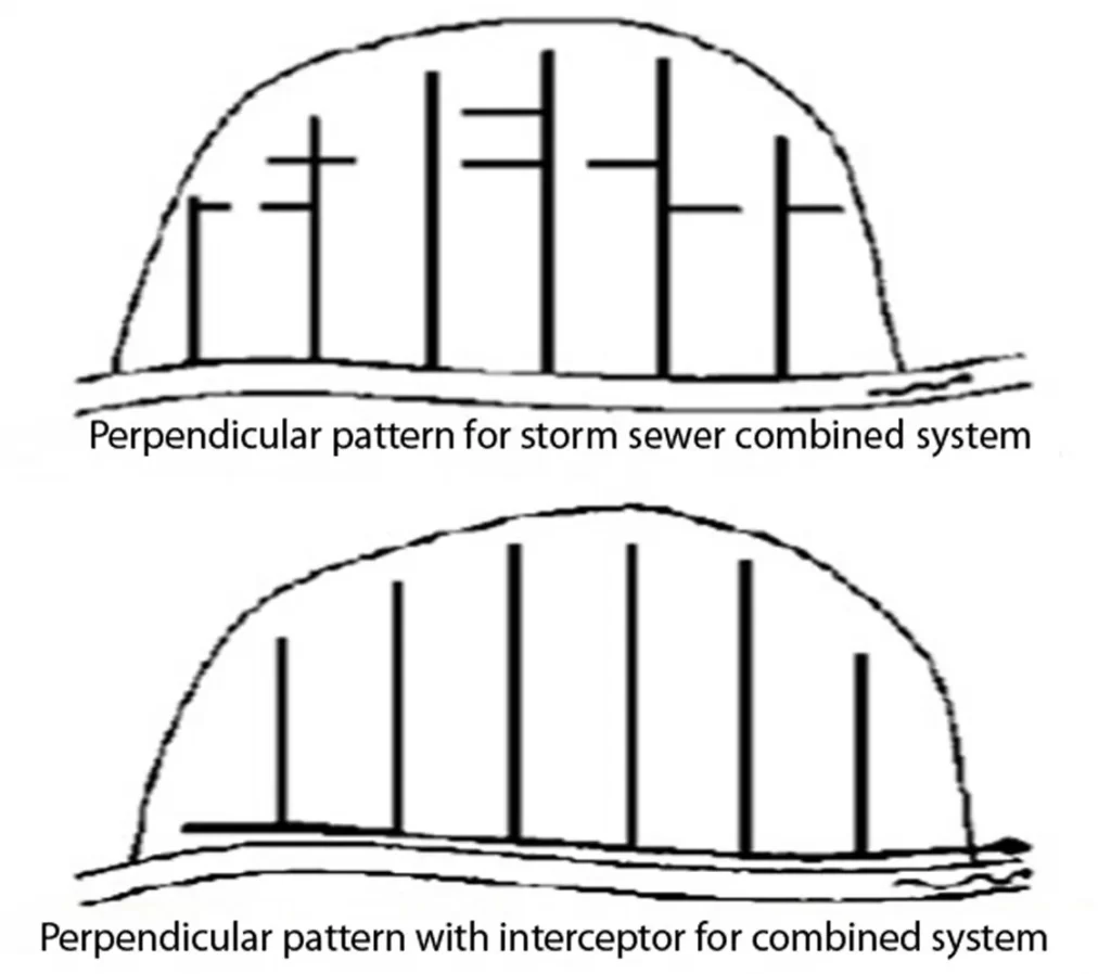
Patterns of collection system
- Perpendicular pattern
- Interceptor pattern
- Radial Pattern
- Fan pattern
- Zone pattern

5) Wastewater Treatment
Types of treatment systems include:
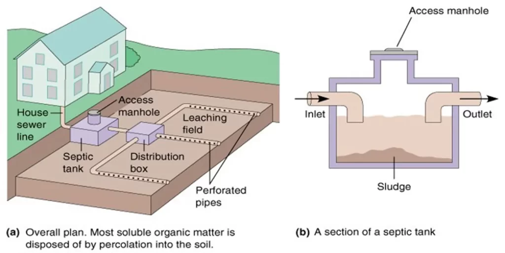
- Septic Tanks typically treat small volumes of waste (e.g., from a single household, small commercial/industrial)
- WWTPs (Wastewater Treatment Plants) typically treat larger volumes of municipal or industrial waste.
Septic Tanks
- Suitability determined by soil type, depth to water table, depth to bedrock and topography
- Commonly fail due to poor soil drainage
- Potential contaminants: bacteria, heavy metals, nutrients, synthetic organic chemicals (e.g. benzene)
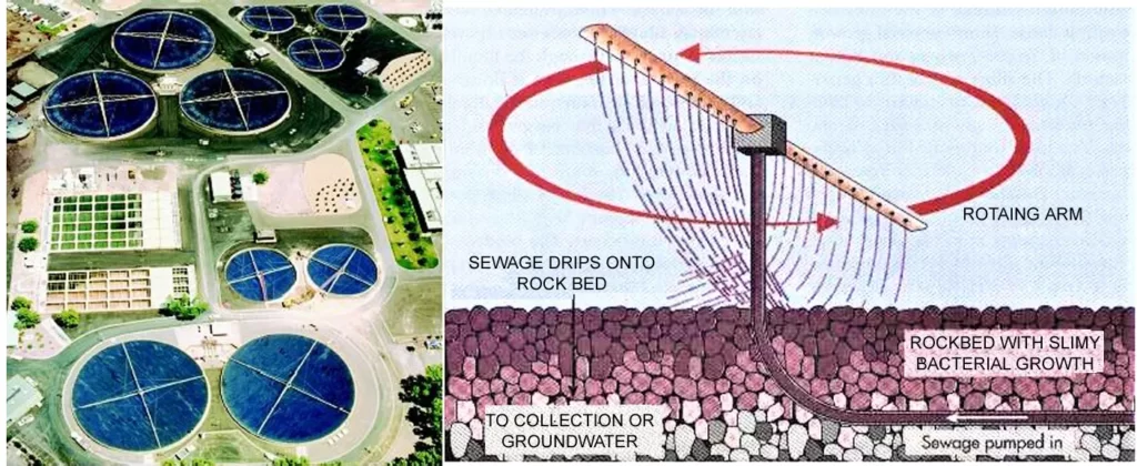
Sewage Treatment
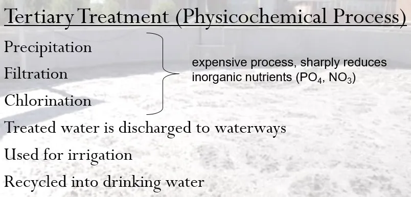
WWTPs (Wastewater Treatment Plants) Sewage Treatment
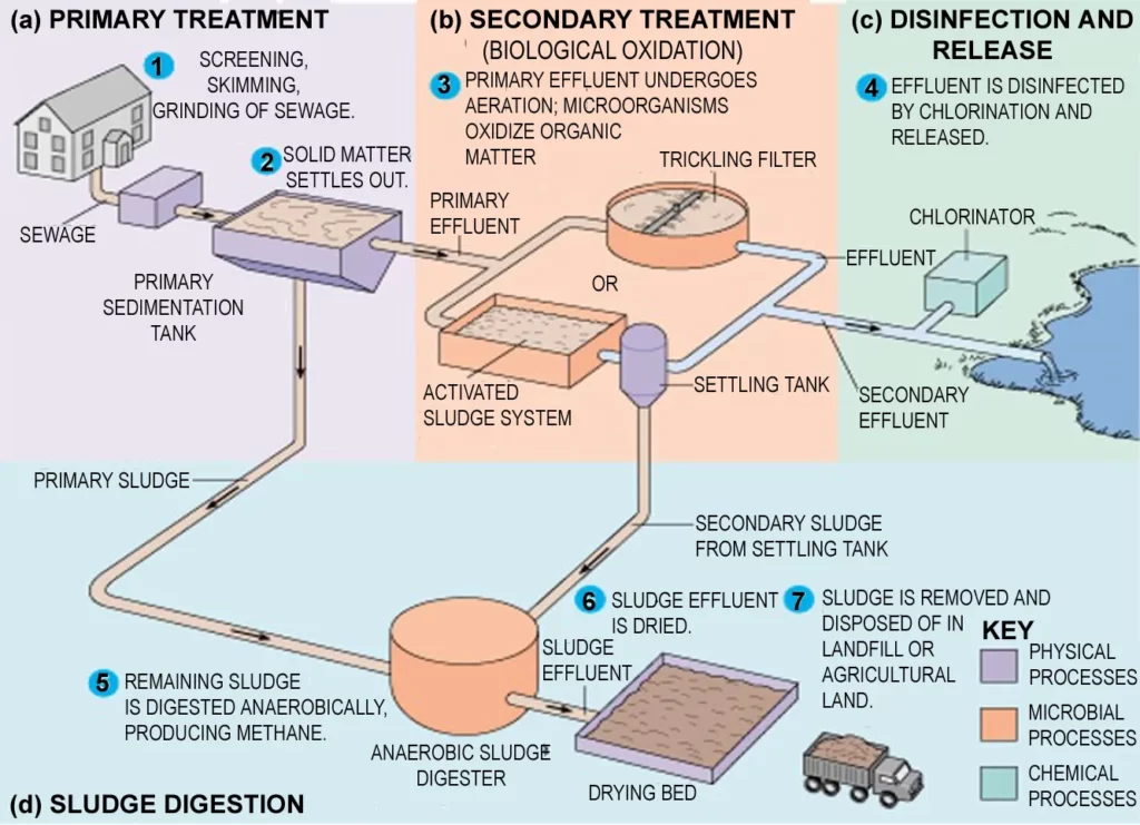
- Aerobic condition are maintained by splashing diffusion and either by force air flowing through the bed or natural convection of air if the filter medium is porous
It’s important to note that sewerage systems in tall buildings require regular maintenance and inspection to ensure they are functioning correctly. Failure to do so can result in blockages, backups, and other issues that can be costly and dangerous. It’s advisable to hire professional plumbers to conduct regular inspections and maintenance to keep the system functioning efficiently.