If you want to know about the technical challenges for tall building or history of tall building or sitting of multistorey building, please click the link.
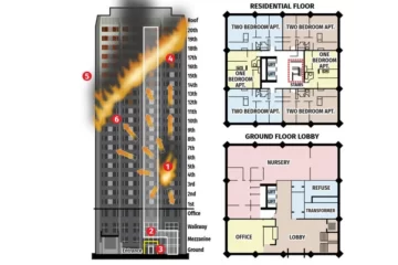
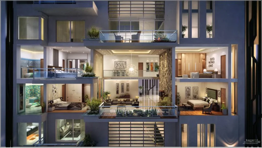
Tall buildings present a range of technical challenges that must be addressed during the design, construction, and operation of the building.
There are many technical challenges of tall buildings.
- Types of loads and force faced by tall buildings.
- Types of Structural System
- Damping System in tall buildings
1) Dead load
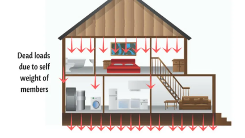
- Permanent loads which are carried to the structure throughout their lifespan
2) Thumb rule to calculate dead load of building
- The dead loads are calculated from the member sizes and estimated material densities. Unit weight of building materials can be estimated in accordance with IS : 875 (Part 1).
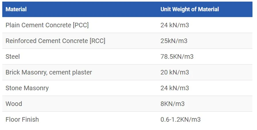
Column:
- Width = .350m, Height = 10m, Breadth = .350m
- Dead Load = Volume x Unit weight = .350 x .350 x 10 x 25 = 30.65 KN
3) Live load / imposed / sudden loads
- The live load includes the weight of furniture, people occupying the floor, etc.
4) Thumb rule to calculate live load of building
| Types of floors | Minimum Live load KN/m2 |
| Floors in houses, hospital wards, dormitories |
2.0 |
| Office floors other than entrance halls | 2.5 & 4.0 |
| Shops, educational buildings, assembly buildings, restaurants | |
| office floors for storage, assembly floor space without seating, public rooms in hotels, dance halls, waiting halls |
5 |
| Stairs, landings, balconies and corridors for floors but not liable to overcrowding | 3 |
| Stairs, landings, balconies and corridors for floors liable to overcrowding | 5 |
| Flat slabs, sloped roofs | 0.75-1.5 |
5) Snow load

- Calculation or Determination of Snow loads on a structure:
- S= μS0
Where,
- S = Design snow load, μ = Shape coefficient (1 uniform thickness roof & 0.8 or less for others roof), S0 = Ground snow load.

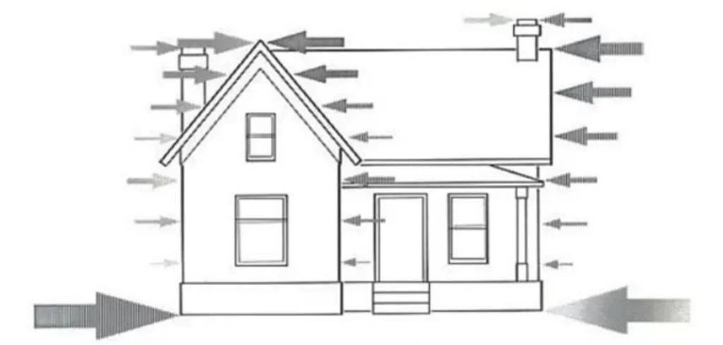
6) Wind load
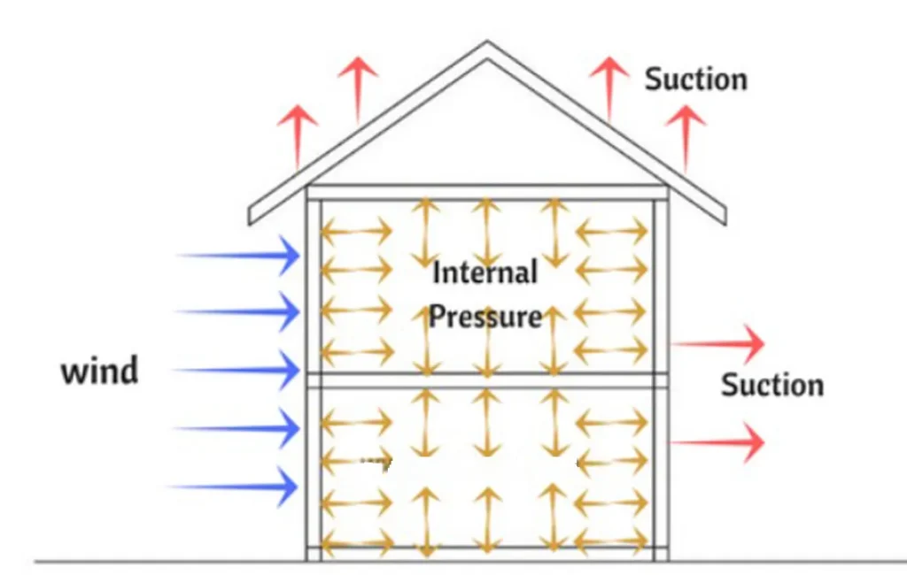

- Where Pz Is in N/m2 at height Z and Vz is in m/sec.
- Up to the height of 30m, the wind pressure is considered to act uniformly. Above 30m the wind pressure may increases.
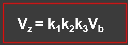
Where
- k1 = Risk coefficient, k2 = Coefficient based on terrain, height and structure size, k3 = Topography factor
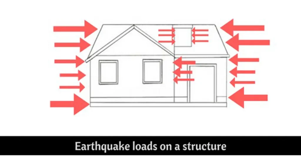
7) Earthquake Load
8) Special loads
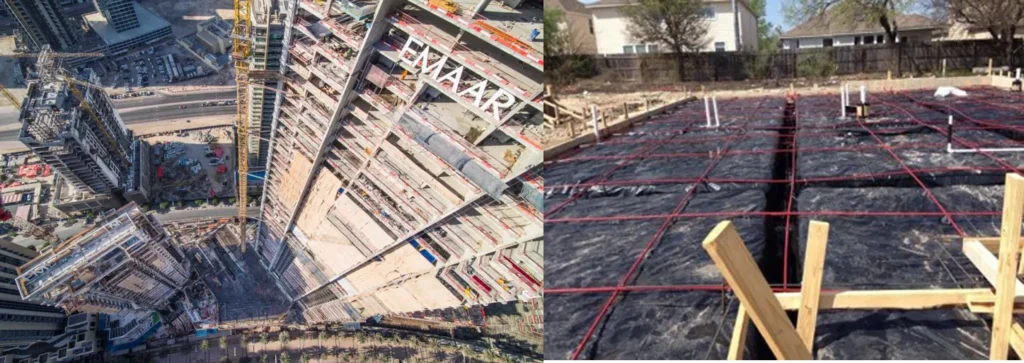
Foundation Movement
Regardless to the type of foundation, there are two common reasons for foundation movement:
- Response to soil volume change (shrink, swell or settle)
- Response to loading (settlement of foundation due to load on soils)
Elastic Axial Shortening
- CAUSES – Concrete, Steel
Vibration
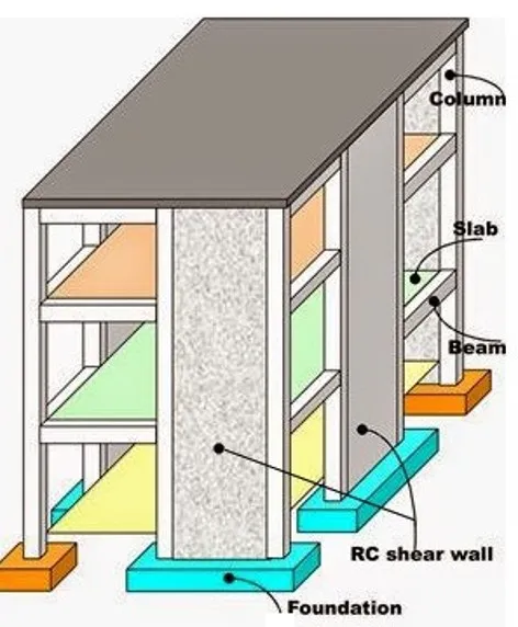
9) Structural system
- Braced frame structural system
- Rigid frame structural system
- Wall-frame system (dual system)
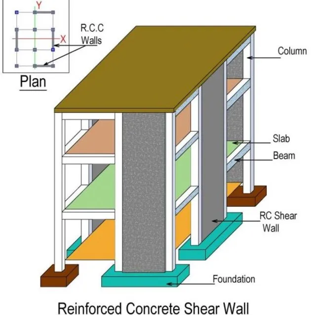
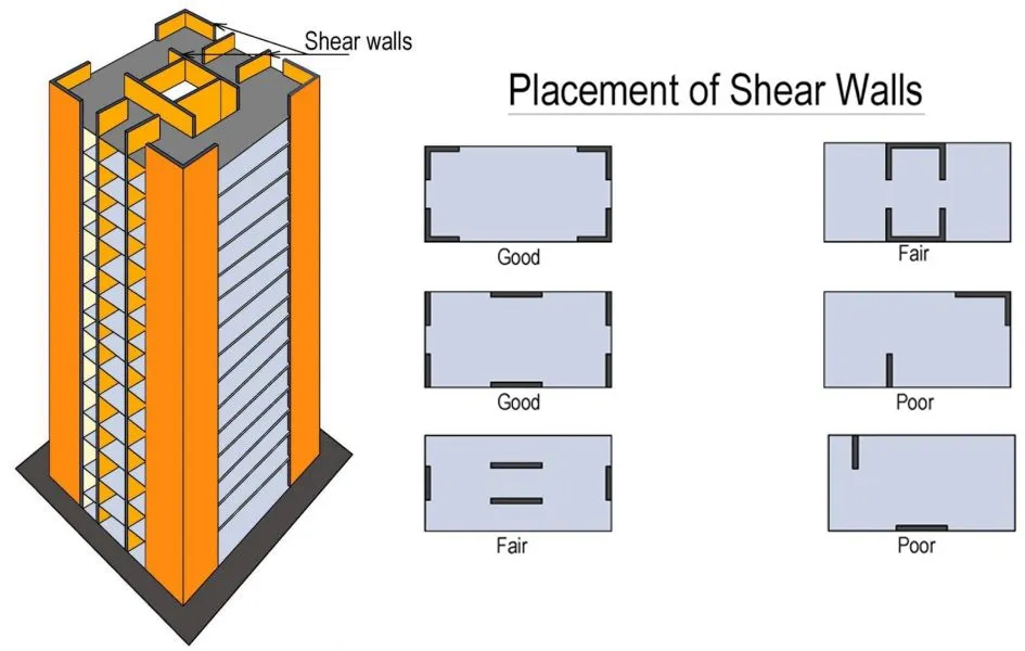
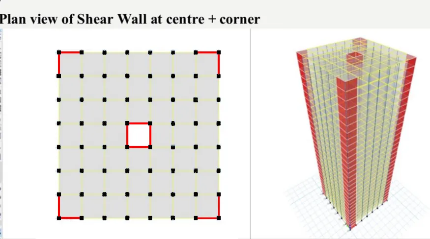
- Shear wall system
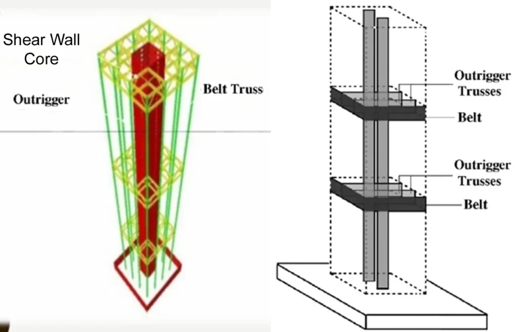
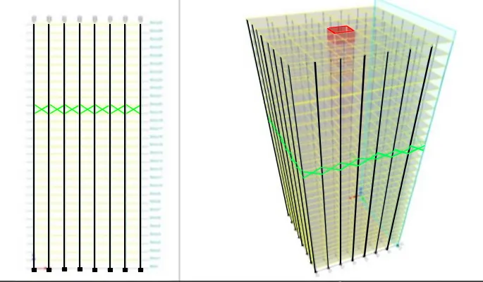
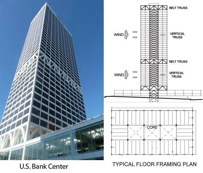
- Core and outrigger structural system
- In-filled frame structural system
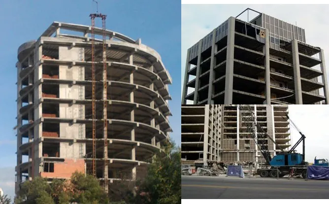
- Flat plate and flat slab structural system
- Tube structural system
- Coupled wall system
- Hybrid structural system
i) Rigid Frame Structure
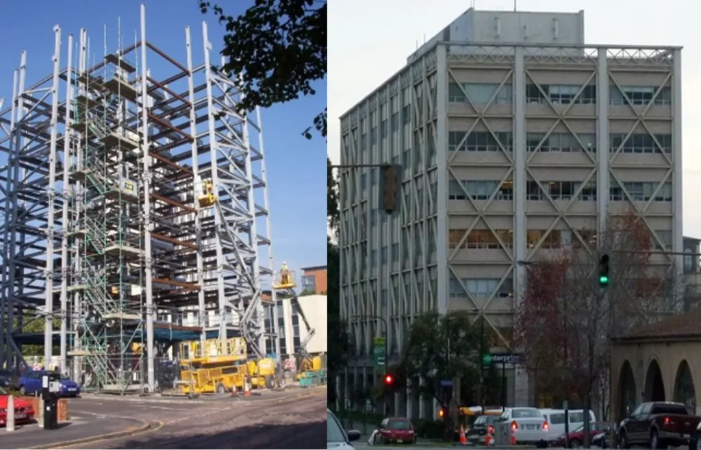
ii) Braced Frame Structure
iii) Wall Frame Structure (Dual System)
iv) Shear Wall System
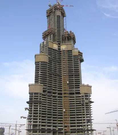
v) Core and Outrigger System
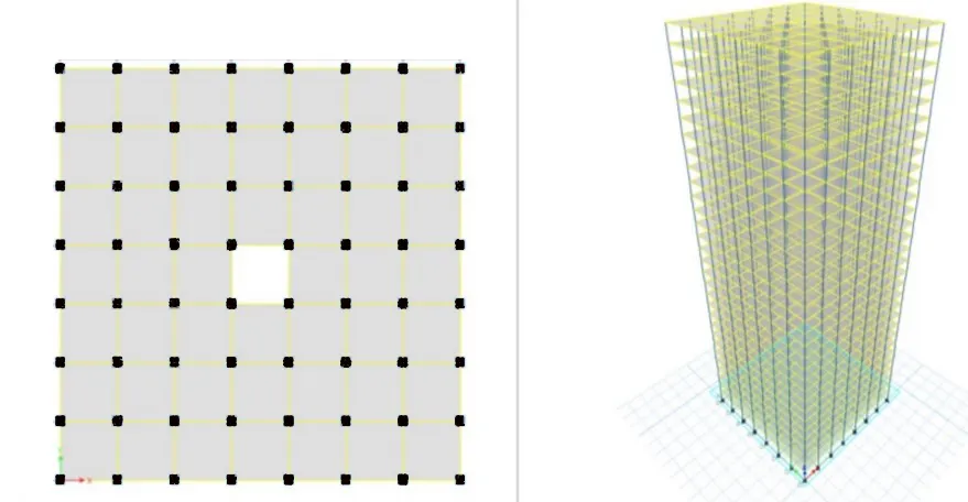
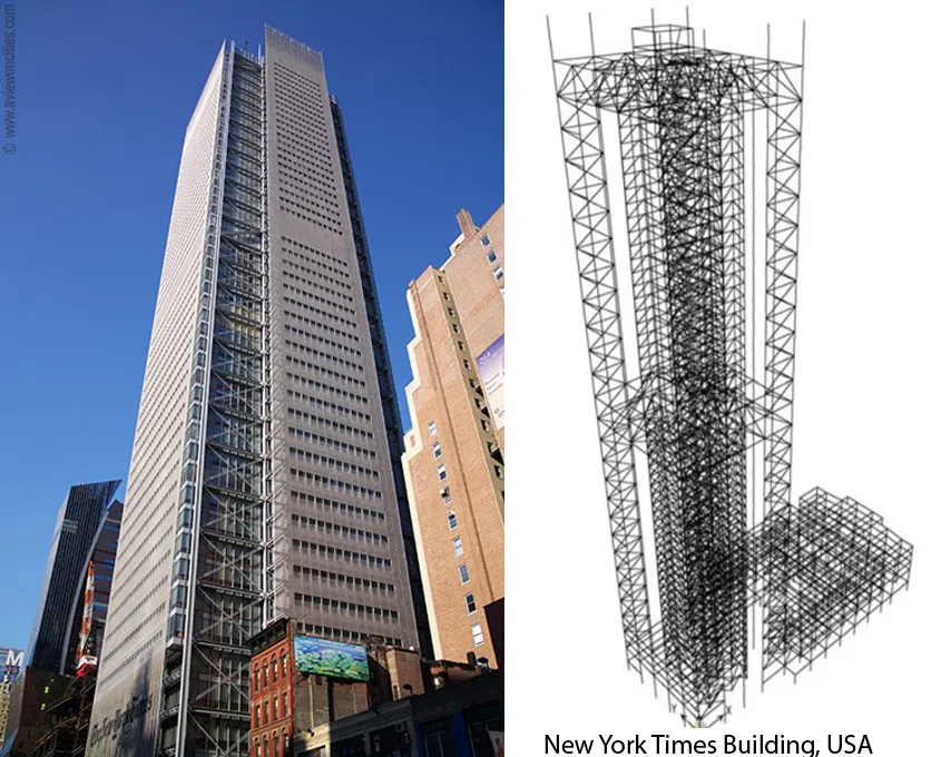
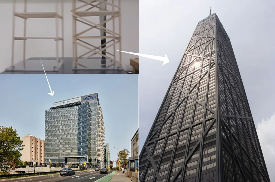
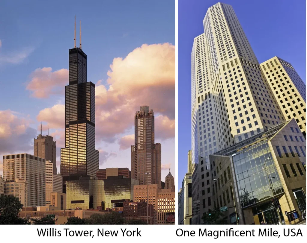
vi) Tube structural system
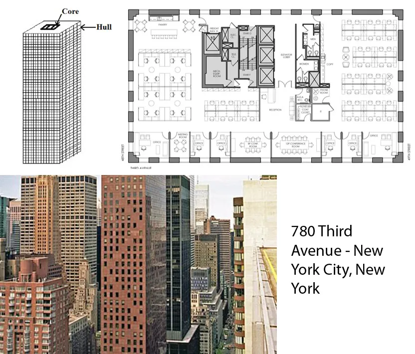
- Framed Tubes Structure System
- Trussed Tube Structure System
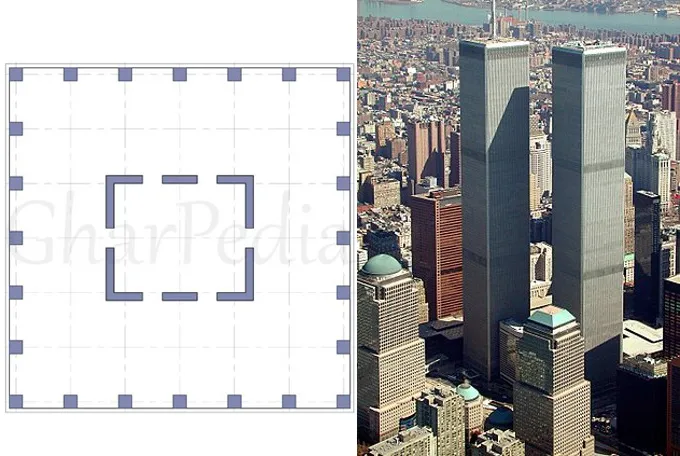
- Tube in Tube
- Bundles Tube
- Hybrid System
a) Frames Tube System
b) Trussed tube

c) Tube in Tube System
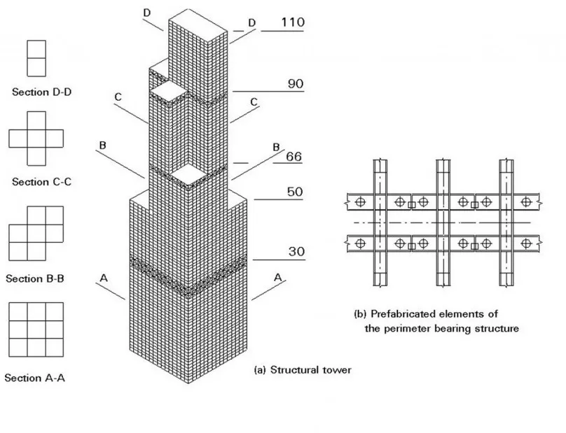
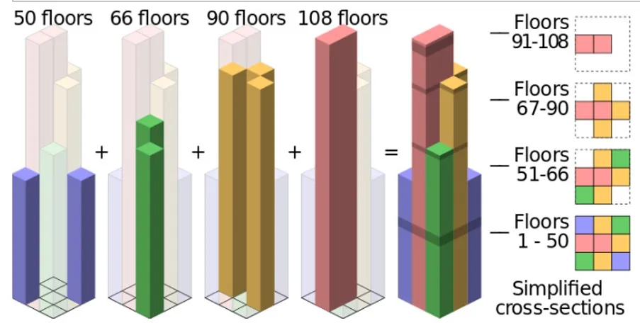
d) Bundled Tube System
e) Hybrid System

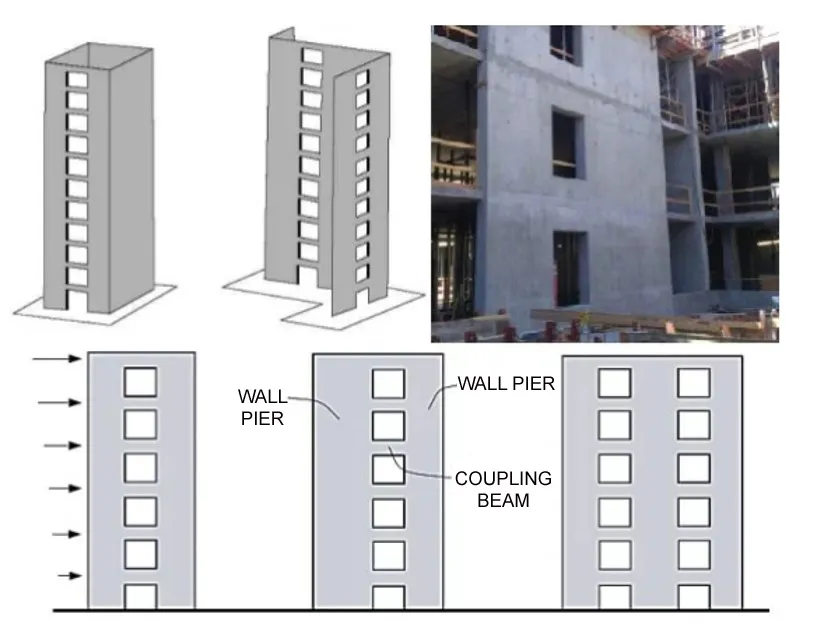
vii) Coupled Wall System
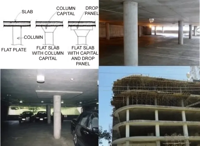
viii) Flat plate and flat slab structural system
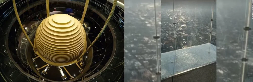
10) Damping in Tall Building

- Damping is the phenomenon in physics whereby energy in the form of vibration is taken from the oscillating system.

Overall, the design, construction, and operation of tall buildings require careful consideration of a range of technical challenges to ensure their safety, functionality, and comfort for occupants.