If you want to know about the scale and proportion in architecture or theory of proportion or installation of split air conditioners, please click the link.
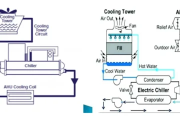
An air distribution system refers to the network of ducts and vents that are designed to deliver conditioned air (i.e., heated or cooled air) from an HVAC (heating, ventilation, and air conditioning) system to different areas of a building.
The air distribution system is an important component of an HVAC system, as it ensures that the conditioned air is distributed evenly and efficiently throughout the building.
- Air distribution refers to the distribution of air to and from conditioned spaces within a building.
- An air distribution system includes all sub-components, such as fans, filters, dampers, ductwork, etc.
- Air distribution systems come in a variety of material types, for example, fiberglass and galvanized metal.
1) Filter
Filters are installed in the air distributor system to clean the contamination in the air due to the dust, smoke, odour, gases and bacteria etc.
- Dry screen filter.
- Viscous impingement
- Fibrous
- Electrostatic dry screen filter
i) Dry screen filter
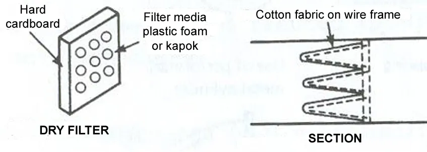
- Dry screen filter depends on the use mesh, to prevent the passage of particles. When the air passes through the mesh the dirt remain at the one side and fresh air pass by. The mesh is renewable, cleanable, and thrown away.
ii) Viscous impingement filter
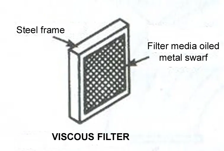
- In such type of filter, the air passes through the mesh coated with oil or grease the particle get adhere to the mesh. This is renewable, cleanable and thrown away mesh.
iii) Fibrous system
- Fibrous system thrown away they have small fibers installed on the surface. These fibers increased the surface area of the mesh and have been more effective
iv) Electrostatic filter
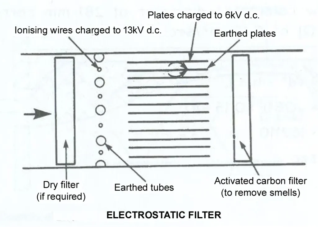
- In such filter the air is passed between the electrically charged plates which give the particles in the air a strong electrical charge, then the air flow between collector plants which have an electrical charge of an opposite nature. The particles are in air are attracted to the collector plate and trap. Cleaned periodically, renewable.
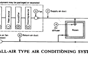
2) Fan
- Fan creates the pressure difference that causes the air to flow in the air distribution system.
Parts –
- Impellers- it is the set of routable blades that push against the air.
- Electric motor- that rotates the impeller.
- Housing- the housing is the casing that encloses the impeller.
Types of fans
- Centrifugal fans
- Axial fans
i) Centrifugal fans
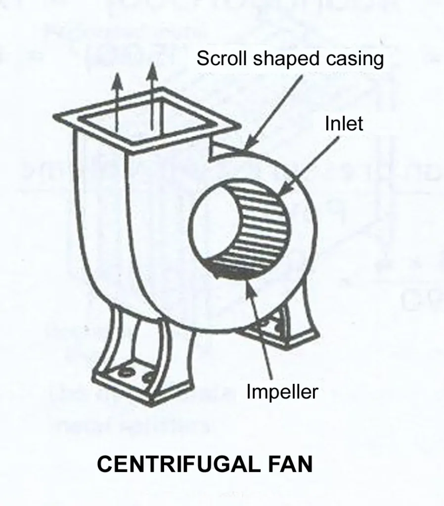
- Centrifugal fans Can produce high pressure and has the capacity for large volume of air. It may have one or two inlets.
- In this type of fan, the air enters the impeller parallel to the axis of rotation and flow radically through the impeller and discharges to the outside edge.
- It consists of cylinder wheel to which no. of blades are fixed in parallel around the circumference of the cylinder.
- The wheel is mounted on shaft or axle. The assembly is placed in e casing which has 1 or 2 wholes concentric to the axle to acts the entry to the air.
- The rotation of the wheel draw the air into the casing and is exposed to the casing outlet and connected to the duct.
- Centrifugal fans can be classified according to the assembly of their blades
Forward curve blade
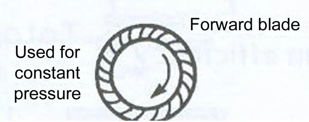
- Forward curve blade tip of blade of this type of fan is inclined towards the direction of rotation. This type of fan is used when high volume of air is required.
Backward curve blade
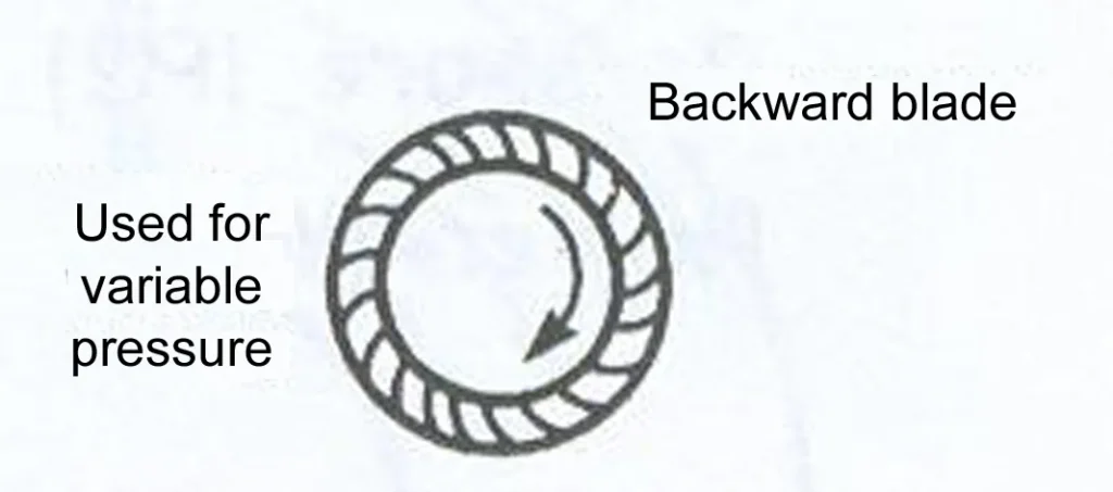
- Backward curve blade tip of blade of this type of fan is inclined backward from the direction of rotation. Quit in operation, runs at satisfactory speed. Satisfactory for small quantity of air.
Radial blade type
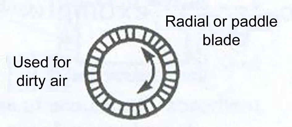
- Radial blade type blades have no curvature. They are well efficient as forward blade type. They can operate in high speed and high pressure.
ii) Axial fan
- In this type of fan air flows through the impeller in the direction parallel to the axis of rotation. on the basis of configuration of the fans hence related the impeller.
Types of axial fan
The propeller types
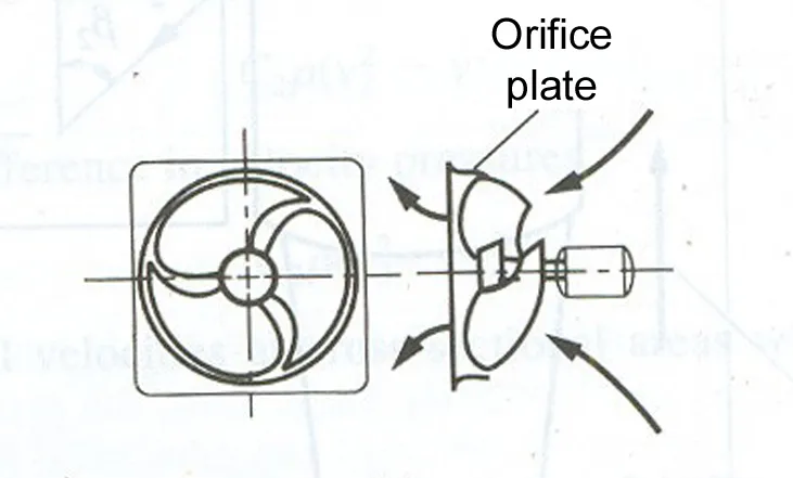
- These fans are often used for small air moving force such to exhaust It is capable of moving good amount of air but less than centrifugal fan and it is nosier than centrifugal fan. It can operate at LP. An impeller having 3 to 6 blades is mounted within a circular ring.
Tube axial type
- The impeller usually has 6- 9 blades mounted within a cylindrical casing. The blades can be airfoil blades or curved sheet metal. The volume flow and fan total pressure can be adjusted for tube axial fans driven directly by motor.
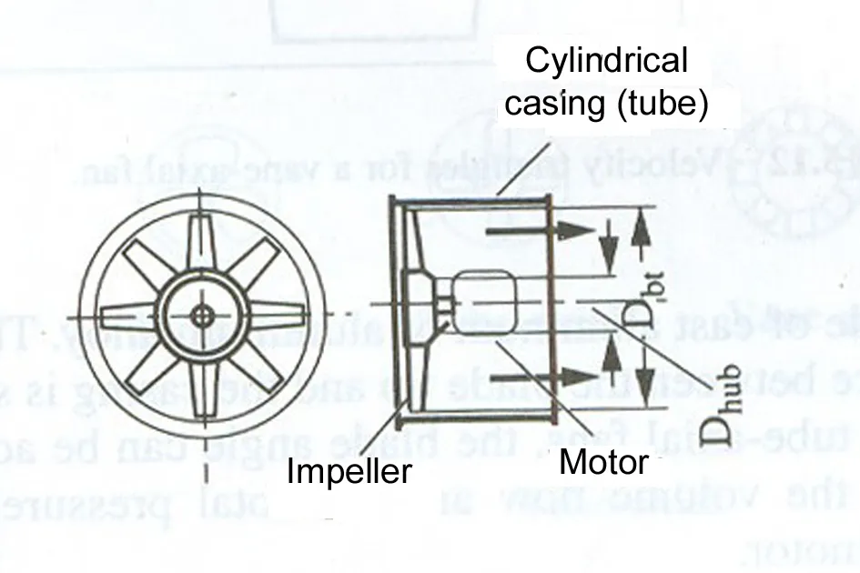
Vane axial fan
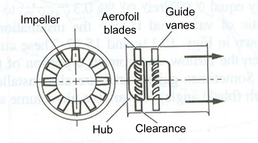
- The impeller usually has 8- 16 blades, usually airfoil blades. This can move the lower amount of air than the propeller and can rotate against the high pressure than propeller.
3) Piping
selection of material of piping depends on:
- Properties of the fluid being carried
- Temperature
- Pressure
- Exposure to oxidation or corrosion.
In addition, cost and availability
Most commonly used in hydronic system-Carbon (black) steel pipe copper tube Joining of steel pipe is usually done with either screwed., welded or flenged fitting Copper tubing. joint is made either by soldering or by flaking.
4) Valves
- GENERAL SERVICE VALVES. Valves are used controlling the fan of the fluis grouped into three classes Stopping flow for stopping the flow of the fluid used for isolating equipment for serve are in isolating sector of a system so that it may be served yet along the rest of the system to operate gate valve
- Regulating flow rate. To adjust flow rate normally:
Example: Globe valve, plug valve, butterfly valve, angle valve, needle valve.
- Limiting flow direction; Valve that allow flow in only one direction are called check valve. reverse flow could occur when the system is not operating particularly if there is a static head of water.
E.g.: swing check
- Vertical lift check or spring-loaded check. Check valves are usually installed act the discharged of a pump.
- Pipe insulation: may be made from natural material such as wool, felt, rock or glass fibers cork and rubber. pipe insulation may be furnished in blanket form or premolded to be size of a pipe to be covered.
- Vapour barriers treated paper or aluminum foil. molding Spong rubber insulation.
- Duct: galvanized steel metal – material.
- Alternative – molded glass fiber Stainless steel, copper or aluminum corrosion resistance material
- Duct insulation: Insulation+vapour barrier Glass fibre+aluminium foil Insulation comes in either size based on blanket.
5) Air supply devices
- Grills and register: They enable control of the air distribution in both direction if needed. Grills with volume control dampers mounted behind the grills called registers.
- Ceiling diffusers: These devices usually consist of a service of separated concentric ring or louvers with a collar or neck to connect to the duct they may be round square or rectangular in shape in addition to those that distribution air equally in all direction they can be designed to distribute air in any desired direction.
- Slot diffusers: This is long strip shaped outlet with one or more narrow opening depending upon the number of bars or vanes.
- Plenum ceiling: hung oiling are available with slots or perforation throughout most or all the ceiling. Which can serve as supply air outlet.
The size, shape, and layout of the ductwork can vary depending on the specific needs of the building and the HVAC system. Proper design, installation, and maintenance of an air distribution system is critical to achieving optimal HVAC system performance, energy efficiency, and indoor air quality.