
If you want to know about the scale and proportion in architecture or theory of proportion or installation of split air conditioners, please click the link.
When designing an HVAC (Heating, Ventilation, and Air Conditioning) system, there are several important considerations to keep in mind. Here are some of the key factors to consider:
1) Desin consideration for heating ventilation and air conditioning
i) Point No. – 1
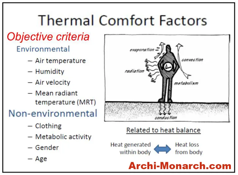
Cooling and heating load estimate shall be carried out prior to design and installation of HVAC equipment. Calculation of cooling and heating load shall take into account the following factors.
- Recommended indoor temperature, relative humidity, air velocity, mean radiant temperature, clothing and activity.
- Outside design conditions as specified in (Point no. – 5).
- Details of building construction and orientation of exposures of building components.
- Fenestration area, thermal properties and shading factors.
- Occupancy – Number of people and their schedule of activities.
- Ventilation – Requirement for fresh air.
- Infiltration, air leakage.
- Internal load – Equipment, computer/server and lighting.
- Effective volume; and
- Occupancy, lighting and equipment schedule.
ii) Point No. – 2
The design of air conditioning, heating and mechanical ventilation system and its associated controls shall also take into account the following.
- Nature of application,
- Permissible control limits,
- Fire safety,
- Opportunities for heat recovery,
- Energy efficiency,
- Filtration standard,
- Hours of use,
- Suitable diversity factor based on usage,
- Outdoor and indoor air quality, and
- Availability of make-up water for cooling towers.
iii) Point No. – 3
- Due consideration shall also be given to air conditioning load encountered during off-peak hours including nighttime and weekend/holidays.
iv) Point No. – 4
- Consideration shall be given to the anticipated future changes, permanent or temporary, in building load and the system shall be so designed that maximum operational efficiency is maintained throughout.
v) Point No. – 5
- Special applications like hospitals/operating theatres, computer rooms, data centers and telecommunication rooms, clean rooms, laboratories, libraries, museums/art galleries, sound recording studios, etc, shall be handled differently.
vi) Point No. – 6
- Computer based hourly load calculation and energy simulation tools may be used for HVAC equipment sizing and to identify effect of various energy conservation measures on energy consumption.
2) Equipment Room for Central Air Conditioning Plant
i) Point No. – 1
- This room shall be located preferably within the building being air conditioned and closer to external wall for facilitating ventilation and equipment movement.
- The equipment may also be installed in a separate service block which should also be located as close as possible to the load/building being conditioned.
- The clear headroom below soffit of beam should be minimum 4.5 m for larger capacity chillers (500 TR and above) and minimum 3.6 m for smaller plants.
ii) Point No. – 2
- The floors of the equipment rooms should be finished smooth.
- For floor loading, the air conditioning engineer should be consulted.
iii) Point No. – 3
- Supporting of pipe within plant room spaces should be normally from the floor.
- However, outside plant room areas, structural provisions shall be made for supporting the water pipes from the floor/ceiling slabs.
- All floor and ceiling supports shall be isolated from the structure to prevent transmission of vibrations.
iv) Point No. – 4
- Equipment rooms, wherever necessary, shall have provision for mechanical ventilation.
- In hot and dry climate, evaporative air cooling may also be considered.
v) Point No. – 5
- Plant machinery in the plant room shall be placed on levelled plain/reinforced cement concrete foundation block and provided with anti-vibratory supports or alternatively on inertia bases.
- Supports for appliances shall be designed and constructed to sustain vertical and horizontal loads within the stress limitations.
- All foundations should be protected from damage by providing epoxy coated angle nosing.
- Seismic restraints requirement should also be considered.
vi) Point No. – 6
- Appropriate sound insulation and noise control measures shall be taken in plant room space.
- Acoustic treatment as may be required shall be provided in plant room space to prevent noise transmission to adjacent occupied areas.
vii) Point No. – 7
- In case air conditioning plant room is located in basement, equipment movement route shall be planned to facilitate future replacement and maintenance.
- Service ramps or hatch in ground floor slab should be provided in such cases.
- Fire egress and emergency battery backup lighting shall be provided for the plant room operator.
viii) Point No. – 8
- Floor drain channels or dedicated drain pipes in slope shall be provided within plant room space for effective disposal of waste water, if necessary by automatic level controlled sump pumps.
- Fresh water connection may also be provided in the air conditioning plant room.
ix) Point No. – 9
Thermal Energy Storage
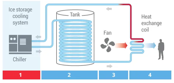
- Thermal storage may be used for limiting maximum demand, by controlling peak electricity load through reduction of chiller capacity, and by taking advantage of high system efficiency during low ambient conditions.
- Thermal storage will also help in reducing operating cost by using differential time-of-the day power tariff, where applicable.
- In case of central plant designed with thermal energy storage, its location shall be decided in consultation with the air conditioning engineer.
- For roof top installations, structural provision shall take into account load coming on the building/structure due to the same.
- For open area surface installation, horizontal or vertical system options shall be considered and approach ladders for manholes provided.
- Buried installation shall take into account loads due to movement of vehicles above the area.
- Provision for adequate expansion tank and its connection to thermal storage tanks shall be made.
3) Equipment Room for Air Handling Units and Package Units
i) Point No. – 1
- This shall be located as centrally as possible to the conditioned area and contiguous to the corridors or other service areas for carrying air ducts in ceiling spaces.
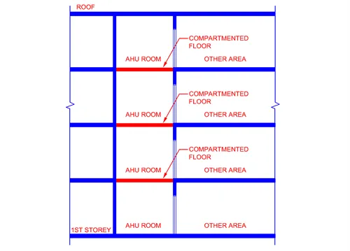
ii) Point No. – 2
- In case of special and high-rise buildings, air handling units shall be provided in accordance with ‘Fire and Life Safety’.
- Air handling unit rooms should preferably be located vertically one above the other.
iii) Point No. – 3
- Provision shall be made for the entry of outdoor ventilation air into air handling unit room.
- For energy conservation, it is desirable to install mechanism for modulating the outdoor air quantity based on demand.
iv) Point No. – 4
- Exterior openings for outdoor air intake and also exhaust outlets shall have louvers having rain protection profile, with volume control damper, pre-filter and bird screen.
v) Point No. – 5
- In all cases, outdoor air intakes shall be so located as to avoid contamination from exhaust outlets and from the sources in concentration greater than normal in the locality in which the building is located.
- It is recommended to maintain minimum 8m separation between outdoor air intake points and exhaust outlets.
vi) Point No. – 6
- Exhaust air from any dwelling unit shall not be circulated/ingress directly or indirectly to any other dwelling unit, to public corridor or into public stairway.
vii) Point No. – 7
- All air handling rooms should have floor drains and if possible, water supply connection.
- The trap in floor drain shall provide a water seal between the air-conditioned space and the drain line.
viii) Point No. – 8
- Supply/return air duct serving other areas shall not be taken through fire exits.
ix) Point No. – 9
- Waterproofing of air handling unit rooms shall be carried out to prevent damage to floor below.
x) Point No. – 10
- The floors should be finished smooth.
- For floor loading, the air conditioning engineer should be consulted.
xi) Point No. – 11
- Structural design should avoid beam obstruction to the passage of supply and return air ducts.
- Adequate ceiling space should be made available outside the air handling unit room to permit installation of supply and return air ducts and fire/smoke dampers at compartment wall crossings.
xii) Point No. – 12
- Appropriate sound insulation and noise control measures shall be taken in air handling unit rooms.
xiii) Point No. – 13
- Access door to air handling unit room shall be single/double leaf type, airtight, opening outwards and should have a sill to prevent flooding of adjacent occupied areas.
- It is desired that access panels in air-conditioned spaces should be provided with tight sealing, gaskets and self-closing devices for air conditioning to be effective.
xiv) Point No. – 14
- It should be possible to isolate the air handling unit room in case of fire.
- The door shall be fire resistant and fire/ smoke dampers shall be provided in supply/return air duct at air handling unit room wall crossings.
- Annular space between the duct and the wall should be fire sealed using appropriate fire resistance rated material.
xv) Point No. – 15
- Fire isolation shall be provided for vertical fresh air duct, connecting several floors.
xvi) Point No. – 16
- It is desirable that individual air handling unit should be installed for each fire compartment, alternately, fire barrier should be provided at each fire separation for air handling units serving more than one compartment.
4) Pipe Shafts
- The shafts carrying chilled water pipes should be located adjacent to air handling unit room or within the room.
- Shaft carrying condensing water pipes to cooling towers located on terrace should be vertically aligned.
- All shafts shall be provided with fire barrier at floor crossings.
- Access to shaft shall be provided at every level, if there is any serviceable component in the shaft.
- In case of tall buildings, care shall be taken for expansion/contraction of pipes while planning the supports.
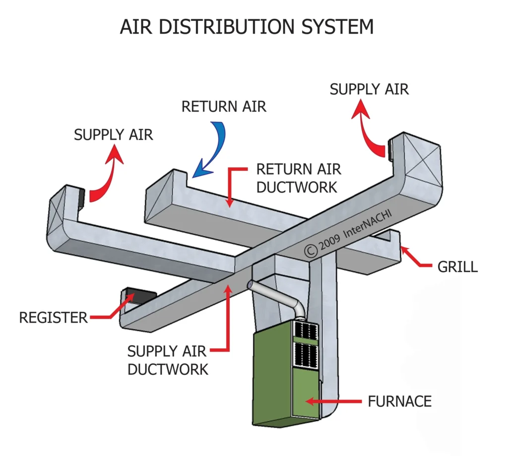
5) Supply Air Ducts and Return Air Ducts
i) Point No. – 1
- The duct supports shall be designed to handle the load and also to take into account seismic considerations.
- The support material should be galvanized steel/aluminium and facilitate ease of installation at site using alternatives such as fully threaded rod/angle section/wire support systems using stud anchors provided in the ceiling slab from drilled holes without damaging the slab or structural member.
ii) Point No. – 2
- If false ceiling is provided, the supports for the duct and the false ceiling, shall be independent.
- Collars for grilles and diffusers shall be taken out only after false ceiling/boxing framework is done and frames for fixing grilles and diffusers have been installed.
- Flexible ducts may be used for making the final connections.
iii) Point No. – 3
- Where a duct penetrates the masonry wall, it shall either be suitably covered on the outside to isolate it from masonry, or an air gap shall be left around it to prevent vibration transmission.
- Further, where a duct passes through a fire resisting compartment/barrier, the annular space shall be sealed with fire sealant to prevent smoke transmission.
6) Cooling Tower
i) Point No. – 1
- Cooling towers are used to dissipate heat from water cooled refrigeration, air conditioning and industrial process systems to the atmosphere.
- Cooling is achieved by evaporating a small proportion of recirculating water into outdoor air stream.
- Cooling towers shall be installed at a place where free flow of atmospheric air is available.
ii) Point No. – 2
- Range of a cooling tower is defined as temperature difference between the entering and leaving water.
- Approach of the cooling tower is the difference between leaving water temperature and the ambient air wet bulb temperature.
iii) Point No. – 3
Selection of Cooling Tower – Following factors shall be considered for selection of cooling tower
- Design wet-bulb temperature and approach of cooling tower. The designer shall endeavour for reducing the approach for maximizing the energy conservation potential.
- Height limitation and aesthetic requirement.
- Location of cooling tower considering possibility of easy drain back from the system.
- Placement with regard to adjacent walls, windows and other buildings, and effects on these from any water carried over by the air stream.
- Vibration and noise levels, particularly during silent hours.
- Material of construction for the tower.
- Direction and flow of prevailing wind.
- Quality of water used for make-up.
- Maintenance and service space availability and
- Ambient air quality.
iv) Point No. – 4
The recommended floor area requirement for various types of cooling tower is as given below.
- Natural draft: 0.15 to 0.20 m2/TR cooling tower
- Mechanical draft: 0.07 to 0.10 m2/TR cooling tower
v) Point No. – 5
- Structural provision for the cooling tower shall be taken into account while designing the building.
- Vibration isolation shall be an important consideration in structural design.
vi) Point No. – 6
- Special care should be taken in design where noise transmitted to the adjoining building can be of serious concern.
- Special vibration control and sound attenuation devices may be required in that case.
- Appropriate sound insulation and noise control measures shall be taken in such cases in accordance.
vii) Point No. – 7
- Certain amount of water is lost from circulating water in the cooling tower, as given below
Evaporation loss
- It is usually about 1 percent of the rate of water circulation.
Drift loss
- The drift loss shall be below 0.1 percent of rate of water circulation.
Blow-down/bleed-off
- The amount of blow- down shall be below 0.8 percent of the total water circulation.
- If simple blow-down is inadequate to control scale formation, chemicals may be added to inhibit corrosion and limit microbiological growth. Provision shall be made to make-up for the loss of circulating water.
viii) Point No. – 8
- Provision for make-up water tank to the cooling tower shall be made.
- Make-up water tank to the cooling tower shall be separate from the tank serving drinking water. Makeup water should be sourced from treated water from sewage treatment, wastewater treatment plant, or from rainwater harvesting.
- Make-up water having contaminants or hardness, which can adversely affect the refrigeration plant life, shall be treated.
- Treated water where hardness as ppm of CaCO3 is reduced to 50 ppm or below is recommended for air conditioning applications.
- Water with pH value less than 5 shall also need to be treated.
- For treatment of water for cooling towers, reference shall be made to the good practice.
ix) Point No. – 9
- Cooling tower should be so located as to eliminate nuisance from drift to adjoining structures.
7) Building Envelope
- The envelope of the building including wall, roof and fenestration shall be planned.
8) Fire Safety
- For fire safety in case of special and high-rise buildings, provisions of ‘Fire and Life Safety’ shall be applicable.
9) Sound Insulation and Noise Control
- Sound insulation and noise control measures for HVAC system shall be in accordance with Building Services Acoustics, Sound Insulation and Noise Control.
10) Energy Conservation
- Designers shall aim for energy efficiency in buildings with the right blend of passive and active design strategies in accordance with Approach to Sustainability, so as to minimise the energy use while ensuring comfort.
To summarize, when designing an HVAC system, designers should consider building size and layout, local climate, energy efficiency, indoor air quality, maintenance and serviceability, cost, occupancy and use, zoning, noise, sustainability, code and regulatory requirements, and future expansion. By taking all of these factors into account, designers can create an HVAC system that meets the needs of the building owner and occupants while also being cost-effective, efficient, and sustainable.