If you want to know about the energy conservation building Code or about the GRIHA and function or about the green building, please click the link.
For ventilation studies
CFD boundary conditions
- The CFD modelling shall be carried out using well-validated software.
- The CFD solver shall have the minimum capability of solving the Navier–Stokes fluid flow equations for a three dimensional incompressible flow at a steady state. Turbulence modelling shall also be included with the minimum requirement of using the standard k-ε turbulence model, coupled with the standard wall function.
- All simulation models shall be carried out under isothermal conditions of 30°C air temperatures at a steady-state condition.
- The computational domain shall include the development of interest and the far field boundary,
which should be located far enough from the building model to avoid artificial acceleration of the flow. As a general guideline, the direction blockage ratio (BRL & BRH) along lateral and vertical directions should be less than 17%.
Note – Blockage ratio is defined as the ratio between the body/geometry and the height and length of the domain.
- The surrounding buildings residing within 500 m distance from the edge of the development of interest should be modelled explicitly.
- Describe the simulation model assumption, limitations, and geometrical simplifications.
- Use zero velocity gradients and zero normal gradients, that is, ‘symmetry’ condition, for all variables at the top and lateral surfaces when the top and lateral boundaries of the domain are far away from the buildings.
- Use zero static pressure as the boundary condition at the outlet surface of computational domain.
- Apply second order discretization schemes.
- In terms of the computational cell quality, the skewness of the cell is advised no greater than 0.9.
- Residuals with at least four orders of magnitudes shall be achieved. Additionally, monitoring points should be defined in the region of interest and the velocities at those points should be recorded to ensure that the flow has reached steady values when simulation is converged properly.
- The naturally ventilated occupied spaces at the lowest level shall be selected for simulation. All
naturally ventilated functional spaces at the selected floor are to be included in the simulation model except for enclosed spaces such as storerooms.
Submittals
Project description : Provide the project details (especially information on naturally ventilated design, building massing / orientation, gross floor area (GFA) of naturally ventilated spaces, percentage of openings and windows, credible source of site information with surrounding buildings, vegetation and terrain, future development, etc.).
- Building type: Describe the building functionality, targeted naturally ventilated spaces, occupants, and transit area.
- Problem statement: Describe naturally ventilated challenges, proposed solution, desired outcome and work scopes from the simulation model.
- Site information: Describe the site information (including surrounding buildings, terrains, and greenery) and illustrate how the geometrical information is incorporated into the simulation model.
- Window modelling: To use the actual window opening size, attach the window schedule and drawing for verification.
Output
- Simulation results for the project for each wind direction considered.
- Static pressure (plan view ground and mid-level and at the level of simulated NV space, isometric views of building).
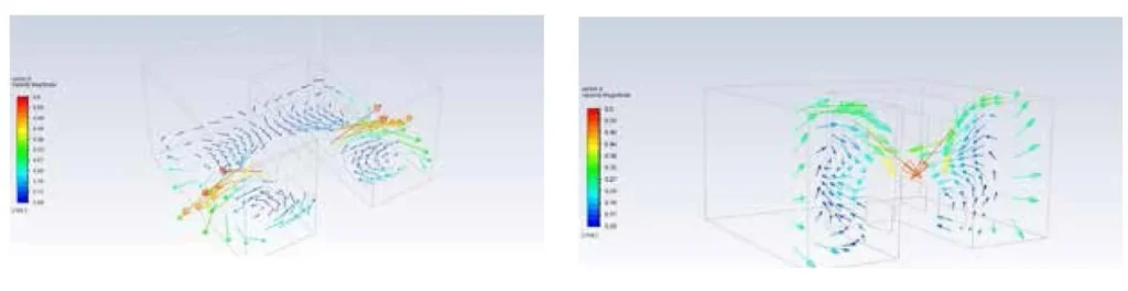
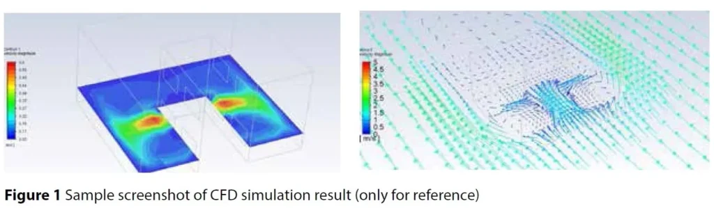
- Velocity vector and contour showing the plan view at ground and mid-level, and at the level of simulated NV space, and a few isometric sectional cut plans to show air-flow patterns across the development.
Note: From the simulation results, the area-weighted average wind velocity of each simulated space shall be determined by considering the air-flow conditions of the applicable areas. The area-weighted average wind velocities of these areas are to be computed at a horizontal plane of 1.2 m above the floor level.
The wind speed as per NBC 2016, Volume 2, Part 8, Section 1, Clause 5.2.3.1.2, Table 9, should be met for the average peak day temperature and RH for 70% of the NV spaces (refer to Figure 1).