If you want to know about the DPC and water proofing or introduction of pile foundation or types of concrete and its uses, please click the link.
Design and analysis of pile foundation involves the determination of the required number, type, and size of piles, as well as the depth and spacing of the piles. The design of a pile foundation also involves the determination of the allowable pile capacity, which is the maximum load that a pile can support without failing. The analysis of a pile foundation is used to evaluate the performance of the foundation under different loads and soil conditions.
1) Design and Analysis of Pile Foundations
Design and analysis is done based on the following:
- Code of practice for the design of sub-structures and foundations of Bridges issued by Railway Board.
- Manual on the Design and Construction of well and pile Foundations issued by RDSO.
Design shall be considered in relation to the nature of ground, manner in which load transfer take place, behavior of group piles and settlement.
i) Spacing of Piles
- Normally centre to centre spacing shall not be more than 4d, where d is the diameter of the piles.
- In case of non-circular section ‘d’ will be the diameter of the circumscribing circle.
- Friction pills shall be sufficiently for apart to ensure that the zones of influence surrounding them do not overlap to such an extent that their carrying capacities are appreciably reduced.
- Generally, the spacing shall not be less than 3d.
- For end bearing piles passing through relatively compressible strata, the spacing shall not be less than 2.5d to avoid heaving of soil.
ii) Load carrying capacity
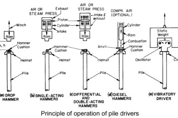
The ultimate bearing capacity of a pile may be assessed by means of –
- Dynamic pile formula, or
- Using data obtained during driving of piles, or
- By static formula on the basis of soil test or
- By a load test.
For non-cohesive soils, Hiley’s formula is more reliable than others (IS:2911 (Part-I) 1969. Hiley’s formula is not reliable for cohesive soils. The static formula should be used with careful judgment, as the mechanics of load transfer from pile to soil is complex. In unknown areas, load test is therefore more desirable. Where scour is anticipated, resistance due to skin friction will be available only below the scour line. When piles are installed through compressible fill or sensitive clay in to under laying hard stratum, a drag down force is generated in the fill or the clay stratum. This must be added to the load.
iii) Factor of safety for Pile Foundation
Factor of safety shall be judiciously chosen after considering the following:
- Reliability of the soil parameters.
- Type of superstructure and nature of loading.
- Possible reduction in the strength of the sub-soil strata arising out of the installation technique.
- Experience of similar structure near the site.
The minimum factor of safety of static formula shall be 3. The final selection of the factor of safety shall take into consideration the total settlement and differential settlement of the structure. The ultimate safe load capacity shall be obtained wherever practical from a load test (I.S. Code:2911=Part-I-1964). A minimum factor of safety shall be 2, on the ultimate load capacity, if obtained from load test.
iv) The factor of safety based on load Test shall be increased in following unfavorable conditions
- Settlement is to be limited or unequal settlement avoided
- Large impact or vibrating loads are expected
- The properties of the soil are expected to deteriorate with time
- The live load on a structure carried by friction piles is a considerable portion of the total load.
The maximum permissible increase over the safe load of a pile on account of wind load is 25%
v) Over Loading of Piles
- An over loading up to 10% of the pile capacity may be allowed on each pile.
- For a group of piles, the maximum over loading on the group shall be restricted to 40% of the allowable load on a single pile of the group.
- This over loading shall not be allowed at the initial design stage.
- The bearing capacity of a pile group may be worked out as under:
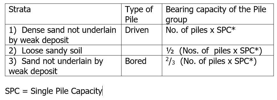
2) Construction Aspects of Bored Cast in Situ Piles
- Generally used for pile dia up to 2500 mm.
- In soft clays and loose sands, bailer and chisel method is used.
- Rotary or percussion type drilling rigs using DMC or RMC method
i) The size of the cutting
- The size of the cutting tool should not be less than the dia. Of the pile by more than 75 mm.
- Use of drilling mud for stabilising the sides of the bore hole is also made.
- Permanent MS liner may be used on top 2-3m to prevent the bore collapse.
ii) Reinforcement
- Minimum area of long reinforcement = 0.4% of the sectional area (calculated on the basis of outside area of the casing or the shaft).
- The minimum clear cover = 40mm.
- The minimum clear distance between main reinforcement = 100mm.
- The minimum dia of the links = 6mm.
- Minimum clear distance between links = 150mm.
iii) Pile Cap
- The clear overhang of pile cap beyond the outermost pile in the group = 100mm to 150mm.
- The pile should project 50mm into the cap concrete.
- The minimum clear cover for the main rein in the cap 60mm.
- The cap is generally cast over a 75 mm thick levelling course.
- For piles of smaller dia and depth up to 6 met. – minimum quantity of cement 350 kg./m3.
- For piles of bigger dia and depth more than 6 met. – minimum quantity of cement 400 kg./m3 and grade M-20.
- 10 % extra cement to be used for under water concreting.
- Slump of concrete 150 to 180 mm.
iv) Alignment control
- For vertical piles a deviation of not more than 1.5 %.
- For raker piles a deviation of not more than 4%.
- Pile should not deviate more than 75 mm or D/4 whichever is less ( for piles less than or equal to 600 mm dia.).
- 75 mm or D/10 whichever is more for more than 600 mm. Dia. Pile.
- In case of single pile in column position, 50mm or D/4 whichever is less for piles up to 600mm dia. 100mm for piles more than 600mm dia.
- Manual chipping of top of the pile may be permitted – after 3 days of pile casting.
- Pneumatic chipping after 7 days of pile casting.
iv) Tremie Concreting
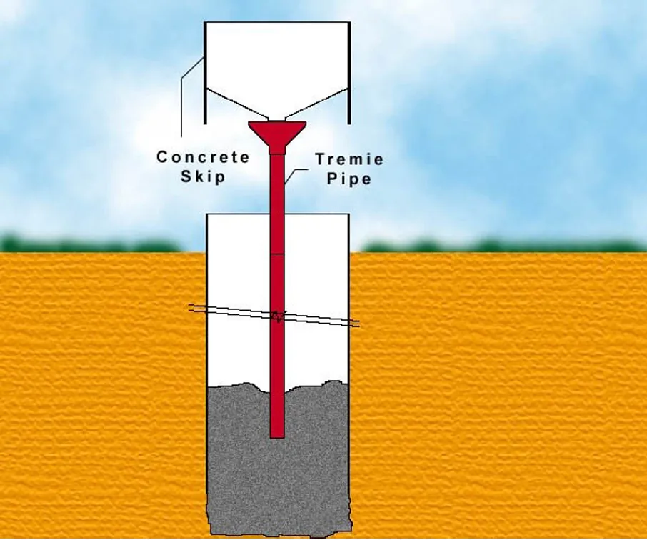
- Concrete should be rich in cement (not less than 370 Kg/m3). Slump = 150mm to 180mm. In under water – casting for full depth or 2 M if non collapsible stratum. If under drilling mud – no casing is required except near the top.
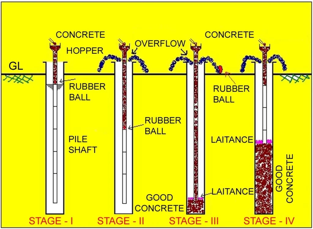
- No leakage at the joints. The tremie pipe should be of min. 200 mm dia. The first charge of the concrete should be placed with a sliding plug pushed down the tube ahead of it. The plug should be taken out and not to be buried into concrete. The tremie pipe should always penetrate well into concrete with an adequate margin. All tremie pipes should be cleaned thoroughly after concreting. The concreting of piles should be uninterrupted. The interruption should not be more than 1 to 2 hours.
- The top of the concrete in a pile shall be brought above the cut off level to permit removal of all laitance and weak concrete. Tremie concreting should be up to piling platform level or to a min. of one meter above the cut off level.
- In other cases – Min. 0.3 met. above the cutoff level , if cutoff level is less than 1.5 met. below the working platform level. For each additional 0.3 met. increase in cut-off level below the working level, the additional coverage of 50 mm.
Tremie Concreting
v) Rock socketing
For the end bearing piles.
- Sound, relatively homogenous rock including granite and gneiss – 1 to 2d.
- Moderately weathered closely formed including schist & slate – 2 to 3d.
- For Soft rock- 3 to 4d
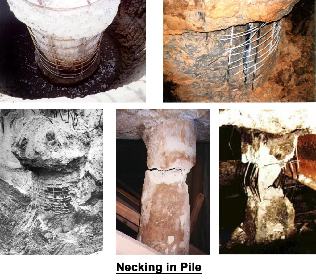
v) Problems in bored cast in situ pile construction
- Overbreak
- Base of bore hole
- Extracting temporary casing
- Soft ground
- Drilling mud
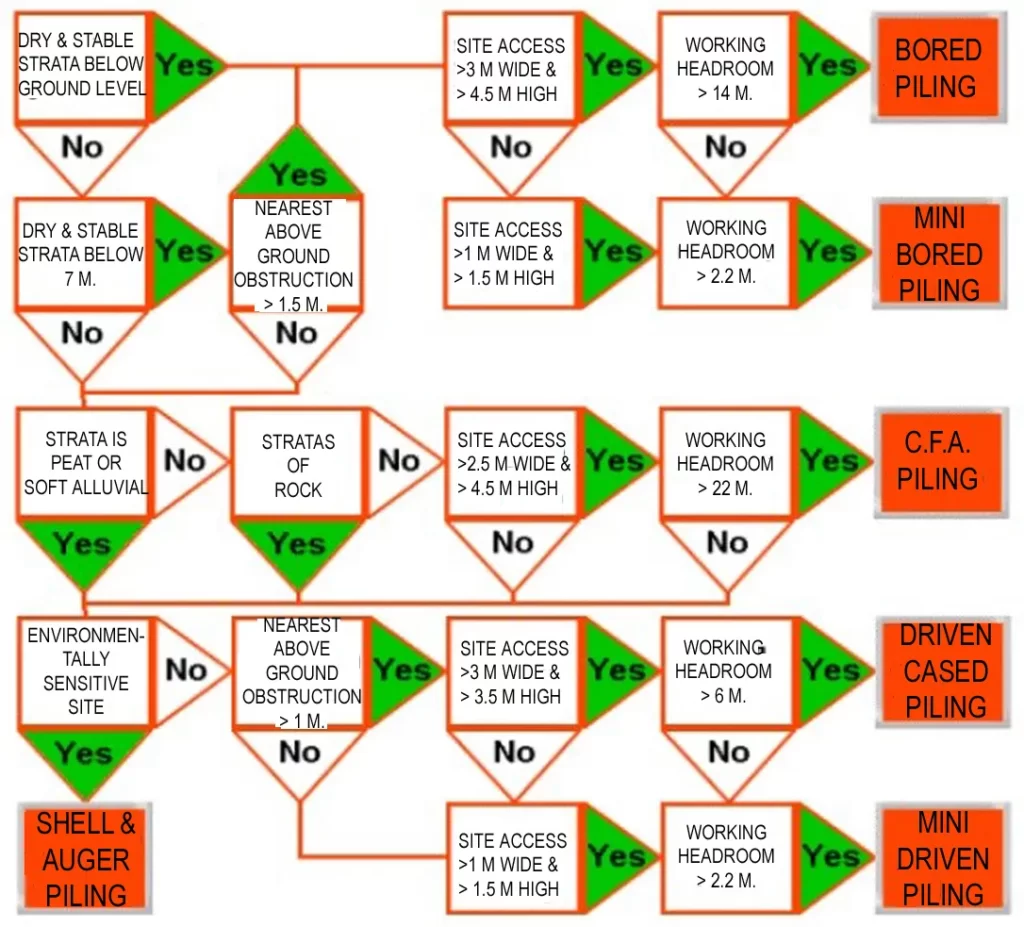
vi) Flow Chart for Pile Selection
3) Site Investigations
- As and when a site investigations is planned it is not always certain that piled foundation will be necessary.
- Therefore the program for the site work should follow the usual pattern for a foundation investigation with bore holes that are sufficient in number to give proper coverage of the site both laterally and in depth.
- If it became evident from the initial boreholes that piling is required, or is an economical alternative to the use of shallow spread foundations, then special attention should be given to ascertaining the level, and characteristics of a suitable stratum in which the piles can take their bearing the bores should be drilled to a depth of 1.5 times the width of the pile group or 10 mtrs whichever is less below the intended base level of the pile, or 1.5 times the width of the equivalent raft below the base of the raft.
- If the piles can be founded on a strong and relatively incompressible rock formation, then drilling need not be taken deeper than a few meters below rock head to check that there are no layers or lances of weak weathered rock which might impair the base resistance of individual piles.
- However, there must be reliable geological evidence that the bearing stratum is not under lair by weak compressible rocks, or the large boulders is not mistaken for rocks. Cased shell and auger borings followed by rotary case drilling to prove the rock conditions can be costly when drilled in large numbers at the close spacing required to establish a detailed profile.
- Geophysical exploration by seismic refraction on land and by continuous seismic profiling at sea are economical methods for over large areas.
- Geophysical methods are not usually economical for small site areas.
- Trial pits are often a useful adjunct to bore hole exploration for a piling project.
- Cable percussion borings give the most reliable information for piling work.
- Cable percussion or flight auger drilling cannot penetrate large and hard boulders, and it is the usual practical to bring a rotary drill over the hole to core through the boulders, so obtaining information on its size and hardness.
- Rock drilling is desirable to be done by rotary case drilling.
- The most useful in situ test for piling investigation is the standard penetration test.
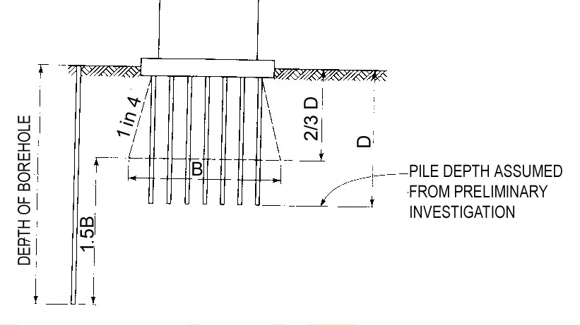
Required depth of boreholes for pile groups in compressible soils
4) Pile Load Test
i) Stress Testing
- Maintained load test.
- Constant Rate of penetration test.
- Dynamic load test.
- Horizontal load Test.
- Cyclic Load Test
ii) Strain Testing
- Low Strain Integrity Testing
- High Strain Integrity Testing
Static Load Test
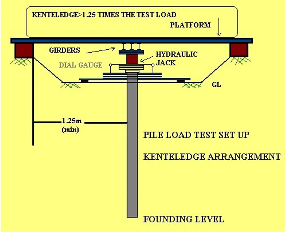
Pile Load Test (Kenteledge Arrangement)
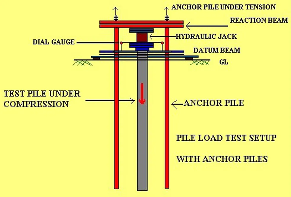
Pile Load Test (With Anchor Piles)
iii) Initial Test
To determine ultimate load capacity and safe load capacity. To study the effect of piling on existing structures. To decide the suitability of piling system. To have a check on calculated load by dynamic or static approaches.
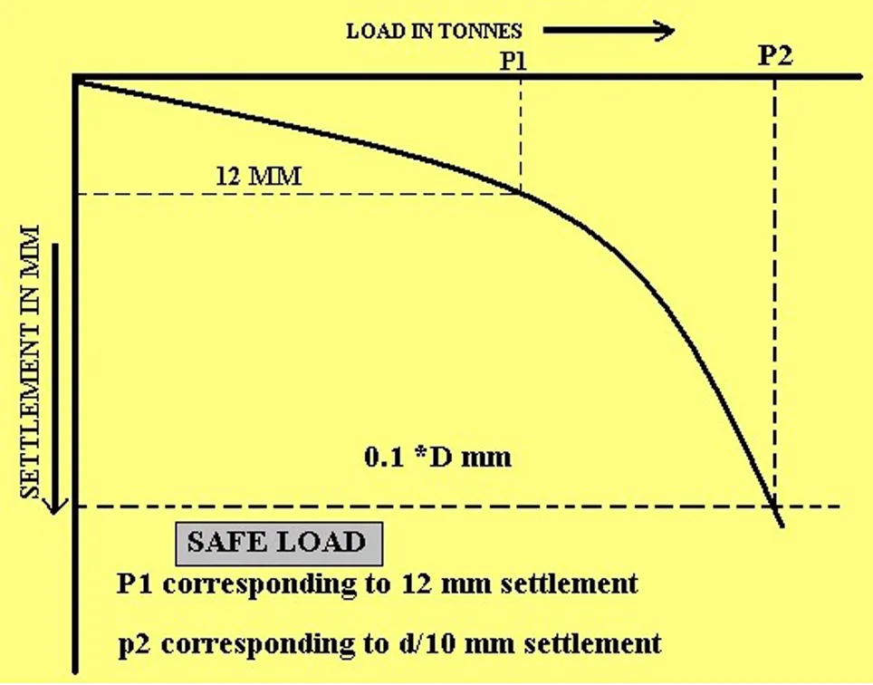
The safe load on a single pile will be least of the following:
- Two third of the final load at which total displacement attains a value of 12mm.
- 50% of the final load at which the total displacement equals 10% of the dia of pile.
The safe load for group of piles:
- Final load at which total displacement is 25 mm.
- Two third of final load at which displacement is 40 mm.
iv) Routine Test
- Test load will be at least 1.5 times the working load.
- Max. Settlement > 12 mm.
- For group of piles max. Settlement > 25 mm.
iv) Initial and routine test
Settlement should be recorded by min. 2 dial gauges for single pile (0.01 mm sensitivity). Gauges should be positioned on datum bars resting on immovable supports at a distance of 3d (Subject to min 1.5 m.) from the edge of pile.
Load Settlement Curve
v) Maintained load test
- Applicable both for initial and routine test –
- Load is applied in increments
- Displacement is measured
- Next increment will be applied when the rate of settlement is less than 0.1 mm in 30 min. Or 0.2 mm in 1 hour or till 2 hours whichever occur first.
- The test load shall be maintained for 24 hours.
Load is increased in stages to some multiple, say 1.5 times or twice the working load with the time settlement curve recorded at each stage of loading and unloading. The maintained load test is best suited for contract works particularly for proof loading test on working piles.
CRP & ML test use the same type of loading arrangements and pile preparation.
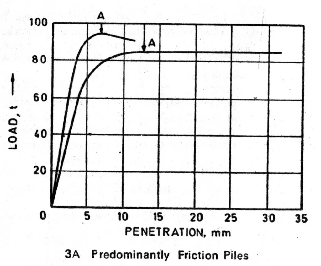
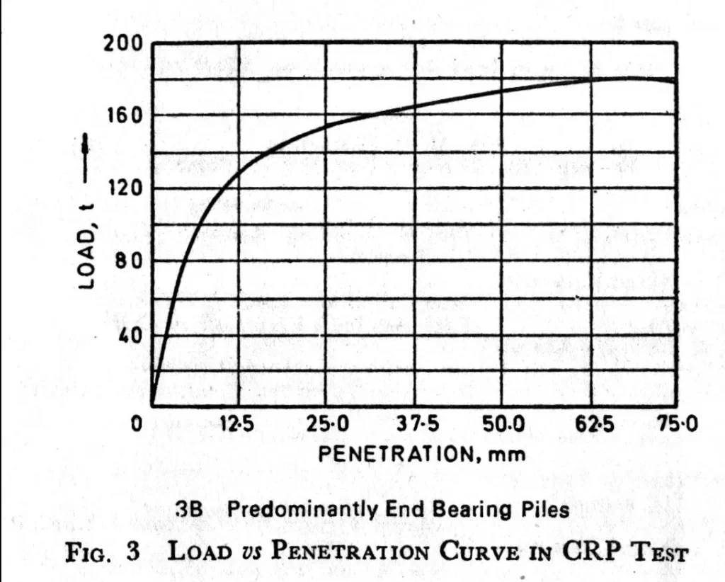
vi) Constant Rate of Penetration Test
- Compressive force is progressively increased to cause the pile to penetrate the soil at a constant rate until failure occurs. CRP is essentially a test to determine the ultimate load on a pile and is therefore applied only to preliminary test piles or research type investigation.
- The method has the advantage of speed in execution and because there is no time for consolidation or creep settlement of the ground, the load settlement curve is easy to interprete. BS-8004 states that penetration rates of 0.75mm/min are suitable for friction piles in clay and 1.55mm/min for piles end bearing in a granular soil.
- The CRP test is not suitable for checking the compliance with specification requirements for the maximum settlement at given stage of loading. There is also difficulty of pricing tenders for this form of load testing since the failure lead on the pile is not known with any certainty until the test is made.
- More suitable for determining ultimate load bearing capacity in comparison to maintained load test. Used for initial test only. Two dial gauges of 0.01mm accuracy are used. Readings of time, penetration and load should be taken at close intervals to give adequate control of the rate of penetration. A rate of penetration of 0.75 mm per min. is suitable for predominantly friction piles. A rate of penetration of 1.5 mm per min. is suitable for predominantly end bearing piles. A curve between load and penetration should be drawn to determine ultimate load bearing capacity.
In summary, the design and analysis of pile foundation is a complex process that requires a thorough understanding of soil mechanics and foundation engineering principles. A successful pile foundation design must take into account the soil conditions, foundation loads, and construction costs, and must be verified using appropriate analysis methods.