
If you want to know about the planning of electrical installation or concept of earthing system or introduction of electricity production, please click the link.
Electrical installations must be carried out safely and in compliance with local regulations and standards. Here are some general guidelines for electrical installation:
1) Residential building electrification
General rules guidelines for wiring of residential installation and positioning of equipment’s.
- Every installation is to be properly protected near the point of entry of supply cables by 2- linked main switch and a fuse unit.
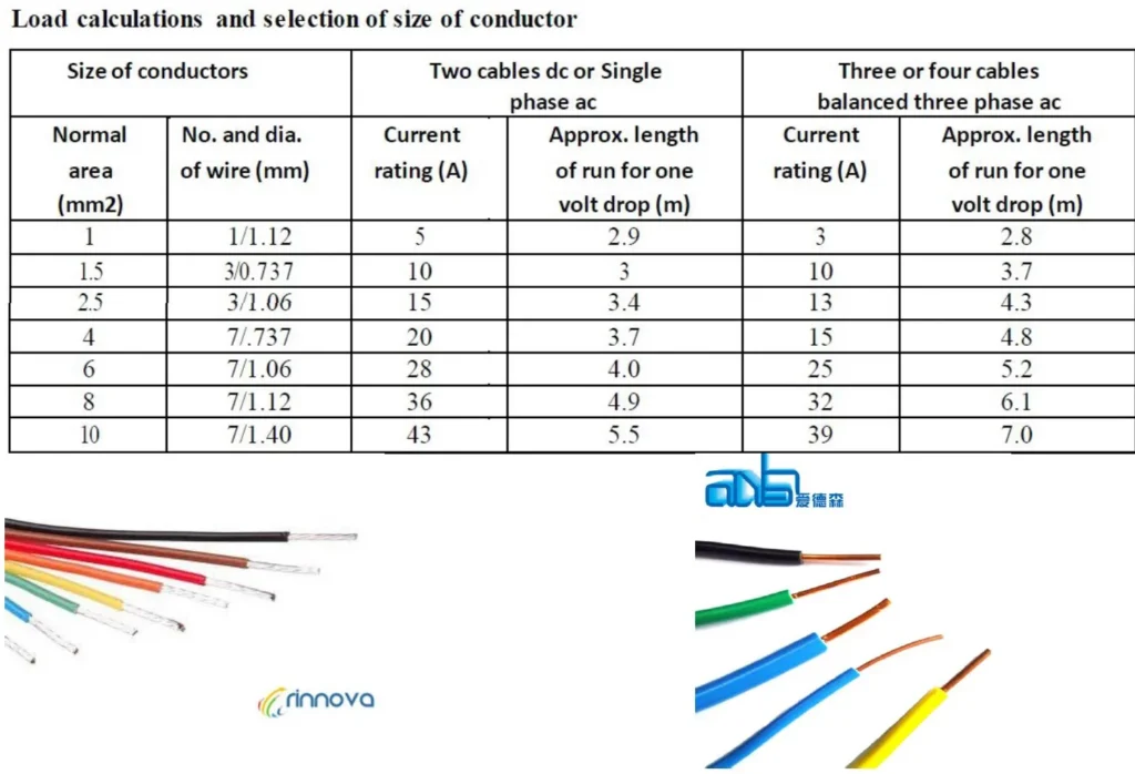
- Conductor used is to be of such a size that it carries load current safely.
- Every sub-circuit is to be connected to a distribution fuse board.
- A switch board is to be installed so that its bottom lies 1.25mts above the floor.
- All plugs & socket outlets are of 3-pin type.
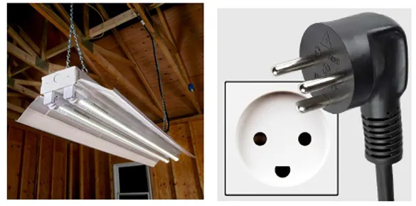
- All incandescent lamps are to be hung at ht of 2.5mt above the floor.
- No fuse or switch is to be provided in earthed conductor.
- In any building, light, fan power wiring is to be kept separately.
- The clearance between the bottom most point of the ceiling fan and the floor shall be not less than 2.4 m. the minimum clearance between the ceiling and the plane of the blade shall be not less than 30 cm.
- Each 15 A socket outlet provided in building for the use of domestic appliances such as AC, water cooler etc.
- Each socket outlet shall be controlled by a switch which shall preferably be located immediately adjacent with socket.
- Ordinary socket outlet may be fixed at any convenient place at a height above 20 cm from the floor level. In a situation where the socket outlet is accessible to children, socket outlet which automatically gets screened by the withdrawal of plug is preferable.
2) Principles of circuit design in lighting and power circuits
- Recommended levels of illumination

Note: Go through ECBC-2017 and NBC volume-II
3) Procedures for designing the circuits and deciding the number of circuits
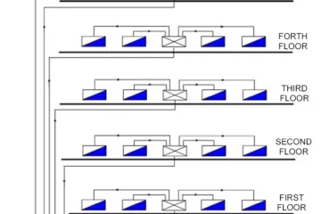
- Balancing of circuit in 3 phase installation shall be planned before hand. It is recommended that all socket outlets in a room are connected to one phase.
- Power sub-circuits shall be kept separate and distinct from light and fan sub-circuit. All wiring shall be on the distribution system with main and branch distribution boards convenient physical and electrical load centers.
- It is recommended to provide at least two lighting sub-circuits in each house. Separate lighting circuits be utilized for all external lightings of steps, walkways, porch, car park terrace etc. with two way switch control.
- Whatever the load to be fed is more than 1 kW, it shall be controlled by an isolator switch or MCB
- Switch boards shall not be erected above gas stove or sink or within 2.5 m of any washing unit in the washing room.
- A switch board shall not be installed at height less than 1.25 m from floor level, unless the front of the switch board is completely enclosed by a door.
- Energy meters shall be installed at a height where it is convenient to note the meter reading; it should preferably not be installed at a height not less than 1 m from the ground.
4) Selection of type of wiring and rating of wires and cables
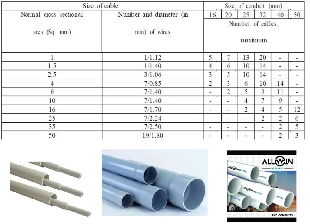
i) Conduit wiring
- Rigid non-metallic conduits are used for surface, recessed and concealed conduit wiring.
- Conductors of ac supply and dc supply shall be bunched in separate conduits. The numbers of insulated cables that may be drawn into the conduit are given in table.
- Maximum permissible number of 1.1 kV grade single core cables that may be drawn into rigid non metallic conduits Conduit shall be fixed by saddles secured to suitable wood plugs or other plugs with screws at an interval of not more than 60 cm. whenever necessary, bends or diversions may be achieved by bending the conduits or by employing normal bends, inspection bends, inspection boxes, elbows or similar fittings.
5) Selection of rating of main switch, distribution board
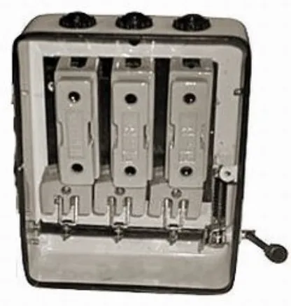
List of standard Iron Clad main switches for domestic purpose:
- DPIC (Double Pole Iron Clad) main switch: 5,15 or 30 A, 250V or DPMCB (Double Pole Miniature Circuit Breaker): 5, 10, 16, 32 and 63 A, 250 V.
- TPIC (Triple Pole Iron Clad) main switch: 30, 60, 100, 200 A, 500 V or TPMCB (Triple Pole Miniature Circuit Breaker): 16, 32 and 63 A, 500 V, beyond this TPMCCB (Triple Pole Molded Case Circuit Breaker): 100, 200, 300 and 500 A, 660 V.
- TPN main switch: 30, 60, 100, 200, 300 A, 500 V or TPNMCB: 16, 32, 63A, 500 V, beyond this TPNMCCB: 100, 200, 300, 500 A, 660 V. Selection of Main Distribution Board: The Main Distribution Board is a fuse box or MCB box where different sub-circuits are terminated. Numbers of sub-circuits are decided based on the total connected load or total number of points.
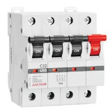
6) Protective switchgear ELCB and MCB and wiring accessories
- There shall be circuit breaker or a linked switch with fuse on each live conductor of the supply mains at the point of entry. The main switch shall be easily accessible and shall be situated near to the termination of service line.
- Branch distribution board shall be provided with a fuse or a miniature circuit breaker (MCB) or both of adequate rating / setting.
- Light and fans may be wired on a common circuit. Such sub-circuit shall not have more than a total of 10 points of light, fan and 5 A socket outlets. The load of such circuit shall be restricted to 800 Watts. Power sub-circuit shall be designed according to the load but in no case shall there be more than two 15 A outlets on each sub-circuit.
- The load on any low voltage sub circuit shall not exceed 3000 Watts. In case of new installation, all circuits and sub-circuits shall be designed by making a provision of 20% increase in load due to any future modification.
- The distribution fuse board shall be located as near as possible to the centre of the load. These shall be fixed in suitable stanchion or wall and shall not be more than 2 m from the floor level.
- All conductors shall be of copper or aluminum. Conductor for final sub-circuit of fan and light wiring shall have a nominal cross sectional area not less than 1 Sq. mm copper and 1.5 Sq. mm aluminium. The cross sectional area for power wiring shall be not less than 2.5 Sq. mm copper, 4 Sq. mm aluminium. The minimum cross sectional area of conductors of flexible cord shall be 0.5 Sq. mm copper.
7) Sequence to be followed for preparing estimate
Sequence to be followed in carrying out the estimate are:
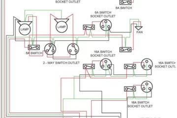
- Wiring layout: Prepare building plan on a suitable scale and mark electrical points, switch boards, main board, meter board, distribution board etc. on the plan using specified symbols. The path of wiring showing connection to each point is marked by a little thick line.
- Calculation of total connected load: The total connected load and hence the total current is calculated for deciding the cable size, rating of main switch board and distribution board.
- Selection of Main Switch: Once the connected load is calculated, the main switch can be conveniently selected from the available standard switch list.
8) List of standard Iron Clad main switches for domestic purpose:
i) DPIC (Double Pole Iron Clad) main switch
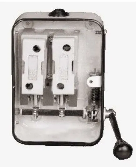
- 5,15 or 30 A, 250V or DPMCB (Double Pole Miniature Circuit Breaker): 5, 10, 16, 32 and 63 A, 250 V
ii) TPIC (Triple Pole Iron Clad) main switch
- 30, 60, 100, 200 A, 500 V or TPMCB (Triple Pole Miniature Circuit Breaker): 16, 32 and 63 A, 500 V, beyond this TPMCCB (Triple Pole Molded Case Circuit Breaker): 100, 200, 300 and 500 A, 660 V
iii) TPIC (Triple Pole Iron Clad) main switch
- 30, 60, 100, 200, 300 A, 500 V or TPNMCB: 16, 32, 63A, 500 V, beyond this TPNMCCB: 100, 200, 300, 500 A, 660 V.
iv) Selection of Main Distribution Board:
- The Main Distribution Board is a fuse box or MCB box where different sub-circuits are terminated. Numbers of sub-circuits are decided based on the total connected load or total number of points.
v) Calculation of length of conduit:
- To avoid duplicity in calculating the length of conduit pipe, this may be calculated in three stages.
(a) The conduit installed from switch board up to horizontal run (HR) including from main switch or DB to HR.
(b) The conduit on walls running parallel to the floor ie, the HR below ceiling.
(c) The conduit installed between HR and ceiling, along ceiling & ceiling to last point on HR. The total length of conduit is calculated by adding the length of conduit obtained from the three stages and including 10% wastage.
vi) Calculation of length of phase wire and neutral wire:
- The phase wire and neutral wire is calculated sub-circuit wise. Once it is calculated, wastage of 15% is included.
vii) Calculation of length of earth wire:
- The earth wire is run along the conduit. The calculations are carried out in length but it is converted in to weight while preparing material table.
viii) Preparing Material Table:
- The material table should be prepared with complete specification of each item.
9) Preparation of detailed estimates and costing of residential installation
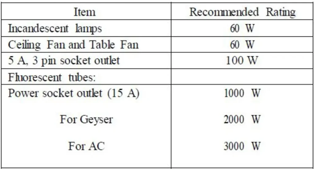
i) Estimation of load requirements
- The electrical installation in this area mainly consists of lights, fans, electrical appliances and other gadgets. In estimating the current to be carried, following ratings are recommended.
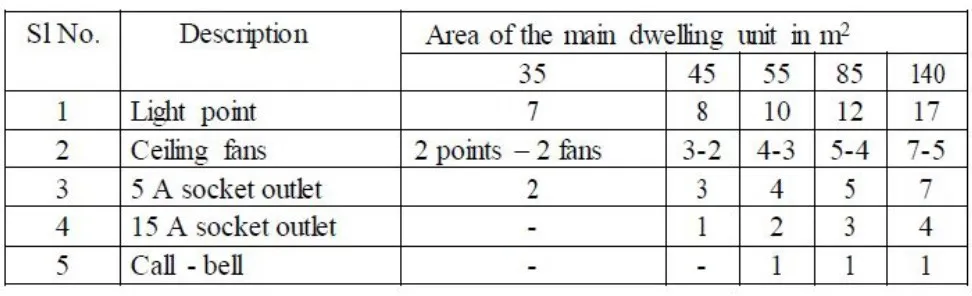
ii) Number of points in branch circuit
- Recommended numbers of points for dwelling units are as follows
iii) Number of socket outlets :
- Recommended schedule of socket outlets for various sub-units are as follows

Remember that electrical work can be dangerous and should only be carried out by licensed professionals. Always prioritize safety and follow local electrical codes and standards.
This handout is extremely good for now and feature use thank you
Well-designed and properly installed electrical systems optimize energy use, reducing waste and lowering energy costs.