
If you want to know about the electrical distribution system or concept of earthing system or Introduction of electricity production, please click the link.
Planning an electrical installation involves several steps that are critical to ensuring the safety and functionality of the system.
1) Considerations for planning electrical wiring installations
- Type of supply, occupancy, envisaged load & earthing arrangement available
- Atmospheric condition which are likely to affect the connections
- Presence of inflammable or explosive dust vapour or gas
- Degree of electrical & mechanical protection necessary
- Importance of continuity of service including the possible need for standby supply
- Probability for modification or future expansion
- Operation & maintenance cost
- Relative cost of various alternative methods
- Safety aspects
- Need for radio & telecommunication interference suppression
- Energy conservation
While planning an installation, consideration should be taken of the anticipated increase in the use of electricity for lighting, general purpose socket-outlet, kitchen heating, etc.
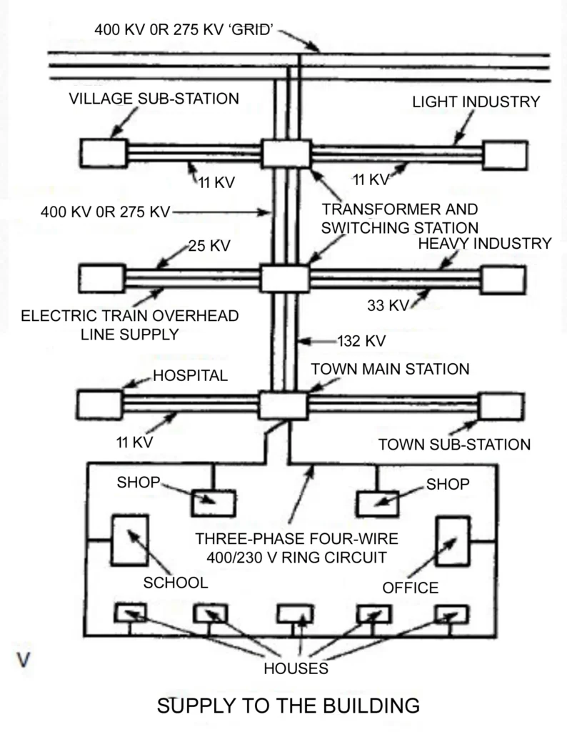
2) Supply of electricity
- The supply to houses & other small buildings is done by an underground/overhead ring circuit from local substations. Supplies to factories and other large buildings or complexes are taken from the 132 or 33 kV main supply.
- Larger buildings and developments will require their own transformer.
- For easy identification, each phase cable has colour coded plastic insulation of brown (red), black (yellow) or grey
(blue). The neutral is colour coded blue (black). Older installations will have colour coded as represented in brackets.
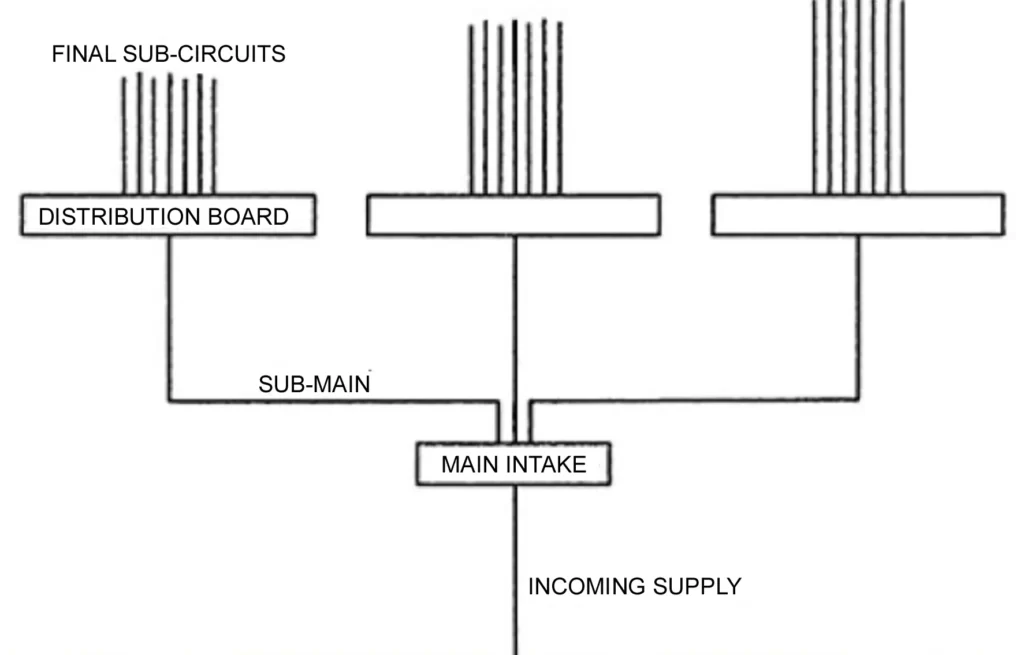
3) Reception & distribution of main supply
- A circuit breaker or load break switch fuse on each live conductor of the supply mains at the point of entry.
- The wiring throughout the installation shall be such that there is no switch or fuse unit in the earthed neutral of conductor.
- The neutral shall also be distinctly marked and an indication of a permanent nature shall be provided to identify the earthed neutral conductor.
- The main switch shall be easily accessible and situated near the termination of service line.
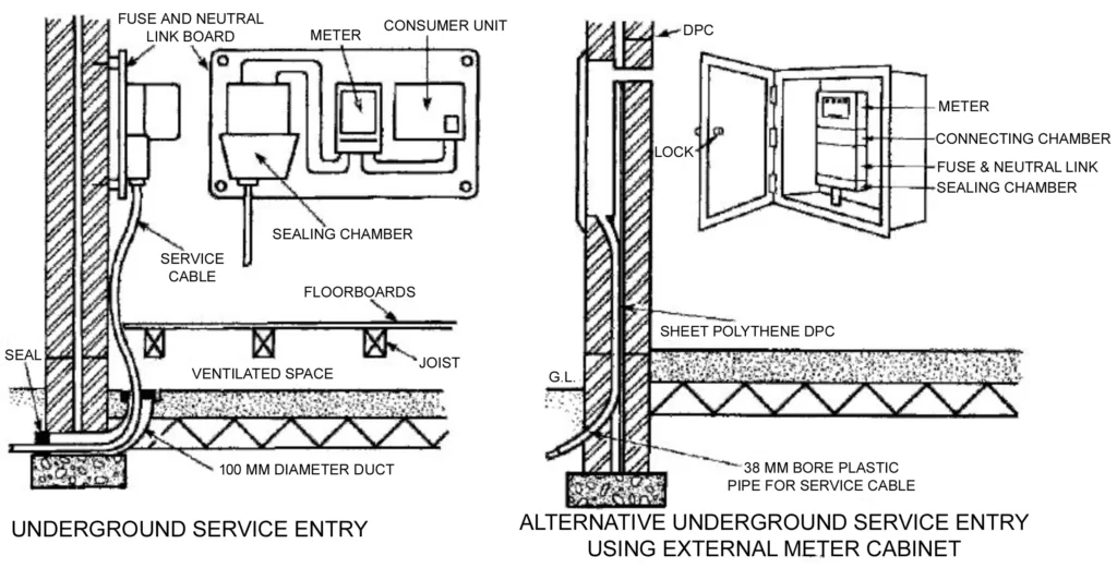
i) Energy meters
- Energy meters shall be installed in residential buildings at such a place which is readily accessible to the owner of the building and the Authority.
- These should be installed at a height where it is convenient to note the meter reading, it should preferably not be installed below 1m from the ground.
- The energy meters should either be provided with a protecting covering, enclosing it completely except the glass window through which the readings are noted or should be mounted inside a completely enclosed panel provided with hinged or sliding doors with arrangement for locking.
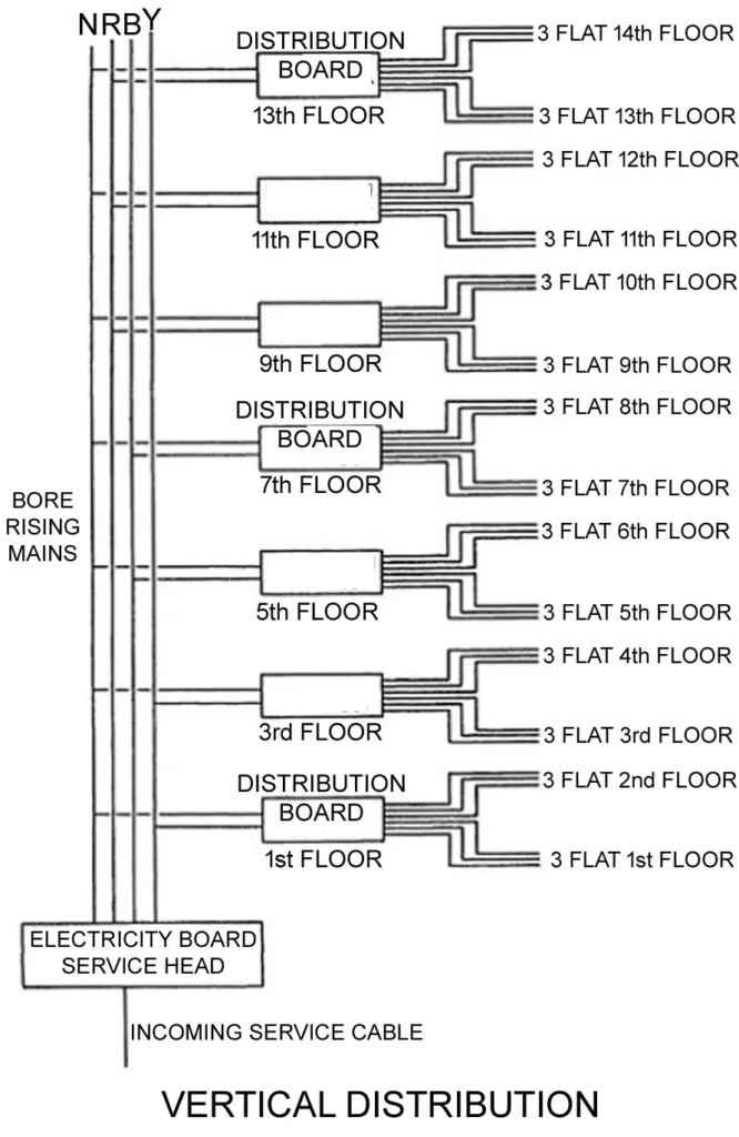
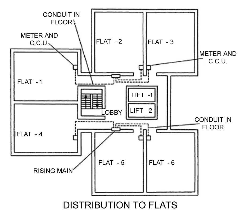
- In multi-storeyed buildings, meters shall be installed with tapping point for meters of the rising main (bus trunking) on individual floors.
ii) Main Switches and Switchboard
- The location of the main board should be such that it is easily accessible for fireman and other personnel to quickly disconnect the supply in case of emergencies. If the room is locked for security, means of emergency access, by schemes such as break glass cupboard, shall be incorporated. Main switch board shall be installed in rooms or cupboards so as to safeguard against operation by unauthorized personnel.
- All main switches shall be either of metal-clad enclosed pattern or of any insulated enclosed pattern which shall be fixed at close proximity to the point of entry of supply. Every switch shall have an environmental protection level rating (IP), so that its operation is satisfactory in the environment of the installation. (Woodwork shall not be used for the construction or mounting of switches and switch boards installed in a building.)
- Switchboards shall be placed only in dry situations and in ventilated rooms and they shall not be placed in the vicinity of storage batteries or exposed to chemical fumes. In damp situation or where inflammable or explosive dust, vapour or gas is likely to be present, the switchboard shall be totally enclosed and shall have adequate degree of protection.
- In some cases, flameproof enclosure may be necessitated by particular Circumstances. Switchboards shall not be erected above gas stoves or sinks, or within 2.5 m or any washing unit in the washing rooms or laundries, or in bathrooms, lavatories or toilets, or kitchens.
- In case of switchboards unavoidably fixed in places likely to be exposed to weather, to drip, or to abnormal moist temperature, the outer casing shall be weatherproof and shall be provided with glands or bushings or adopted to receive screwed conduit, according to the manner in which the cables are run.
iii) Metal-clad switchgear
- Metal-clad switchgear shall preferably be mounted on any of the following types of boards:
Hinged-type metal boards
- These shall consist of a box made of sheet metal not less than 2 mm thick and shall be provided with a hinged cover to enable the board to swing open for examination of the wiring at the back.
- The board shall be securely fixed to the wall by means of rag bolts, plugs, or wooden plugs and shall be provided with a locking arrangement and an earthing stud.
- All wires passing through the metal board shall be protected by a rubber or wooden bush at the entry hole.
Fixed-type metal boards
- These shall consist of an angle or channel iron frame fixed on the wall or on floor and supported on the wall at the top, if necessary. There shall be a clear distance of 1 m in front of the switchboards.
Protected-type switchboard
- A protected switchboard is one where all of the conductors are protected by metal or other enclosures. They may consist of a metal cubicle panel, or an iron frame upon which is mounted metalclad switchgear.
- They usually consist of a main switch, busbars and circuit breakers or fuses controlling outgoing circuits.
Open-type switchboard
- An open type switchboard is one, which has exposed current carrying parts on the front of the switchboard. This type of switchboard is rarely used nowadays but where this exists, a hand rail or barrier has to be provided to prevent unintentional or accidental contact with exposed live parts.
- They must be located in a special switch room or enclosure and only a competent person may have access to these switchboards. These boards may be existing in old installations.
- It is recommended that they be phased out. With the continuously increasing fault power feed due to increases in generation and strengthening of distribution systems, these open boards are a source of accidents.
iv) Recessing of boards
- Where so specified, the switchboards shall be recessed in the wall. Ample room shall be provided at the back for connection and at the front between the switchgear mountings.
v) Marking of apparatus
- Where a board is connected to voltage higher than 250 V, all the apparatus mounted on it shall be marked.
- Three-phases — red, Three-wire system yellow, blue — 2 outer wire, positive red and negative blue 1 Neutral — black 1 Neutral — black.
- Where four-wire three-phase wiring is done, the neutral shall be in one colour and the other three wires in another colour as mentioned above or shall be suitably tagged or sleeved for fool proof identification.
vi) Distribution Boards
- A distribution board comprises of one or more protective devices against over current and ensuring the distribution of electrical energy to the circuits.
- The distribution boards shall be located as near as possible to the centre of the load they are intended to control.
- Distribution board shall provide plenty of wiring space, to allow working as well as to allow keeping the extra length of connecting cables, likely to be required for maintenance.
- Main distribution board shall be provided with a circuit breaker on each pole of each circuit, or a switch with a fuse on the phase or live conductor and a link on the neutral or earthed conductor of each circuit.
vii) Branch Distribution Boards
- Branch distribution boards shall be provided, along with earth leakage protective device (ELCB) (incoming), with a fuse or a miniature circuit breaker or both of adequate rating/setting chosen on the live conductor of each sub-circuit and the earthed neutral conductor shall be connected to a common link and be capable of being disconnected individually for testing purposes.
- At least one spare circuit of the same capacity shall be provided on each branch distribution board.
viii) Branch Distribution Boards
- Further, the individual branching circuits (outgoing) shall be protected against over-current with miniature circuit breaker of adequate rating.
- In residential/industrial lighting installations, the various circuits shall be separated and each circuit shall be
individually protected so that in the event of fault, only the particular circuit gets disconnected. - Circuits shall be separate for installations at higher level such as those in the ceiling and at higher levels, above 1 m, on the walls and for installations at lower level such as sockets for portable or stationery plug in equipments. For devices consuming high power and which are to be supplied through supply cord and plug, separate wiring shall be done. For plug-in equipment provisions shall be made for providing ELCB protection in the distribution board.
- It is preferable to have additional circuit for kitchen and bathrooms. Such sub-circuit shall not have more than a total of ten points of light, fans and 6A socket outlets. The load of such circuit shall be restricted to 800 W. If a separate fan circuit is provided, the number of fans in the circuit shall not exceed ten.
- Power sub-circuit shall be designed according to the load but in no case shall there be more than two 16A outlets on each sub-circuit. The circuits for lighting of common area shall be separate. For large halls 3-wire control with individual control and master control installed near the entrance shall be provided for effective conservation of energy.
- Where daylight would be available, particularly in large halls, lighting in the area near the windows, likely to receive daylight shall have separate controls for lights, so that they can be switched off selectively when daylight is adequate, while keeping the lights in the areas remote from the windows on.
- Circuits for socket outlets may be kept separate from circuits feeding fans and lights. Normally, fans and lights may be wired on a common circuit. In large spaces circuits for fans and lights may also be segregated. Lights may have group control in large halls and industrial areas. While providing group control consideration may be given for the nature of use of the area lit by a group.
- Consideration has to be given for the daylight utilization, while grouping, so that a group feeding areas receiving daylight can be selectively switched off during daylight period.
- The load on any low voltage sub-circuit shall not exceed 3000 W. In case of a new installation, all circuits and sub-circuits shall be designed with an initial load of about 2500 W, so as to allow a provision of 20 percent increase in load due to any future modification. Power sub-circuits shall be designed according to the load, where the circuit is meant for a specific equipment.
- Good practice is to limit a circuit to a maximum of four sockets, where it is expected that there will be diversity due to use of very few sockets in large spaces (example sockets for use of vacuum cleaner).
- General practice is to limit it to two sockets in a circuit, in both residential and non-residential buildings and to provide a single socket on a circuit for a known heavy load appliance such as air conditioner, cooking range etc.
- In wiring installations at special places like construction sites, stadium, shipyards, open yards in industrial plants, etc, where a large number of high wattage lamp may be required, there shall be no restriction of load on any circuit but conductors used in such circuits shall be of adequate size for the load and proper circuit protection shall be provided.
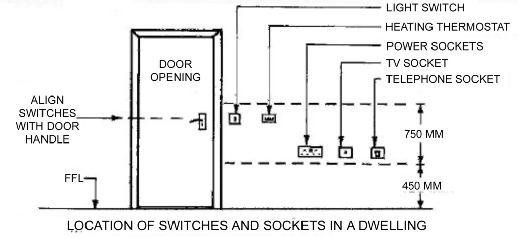
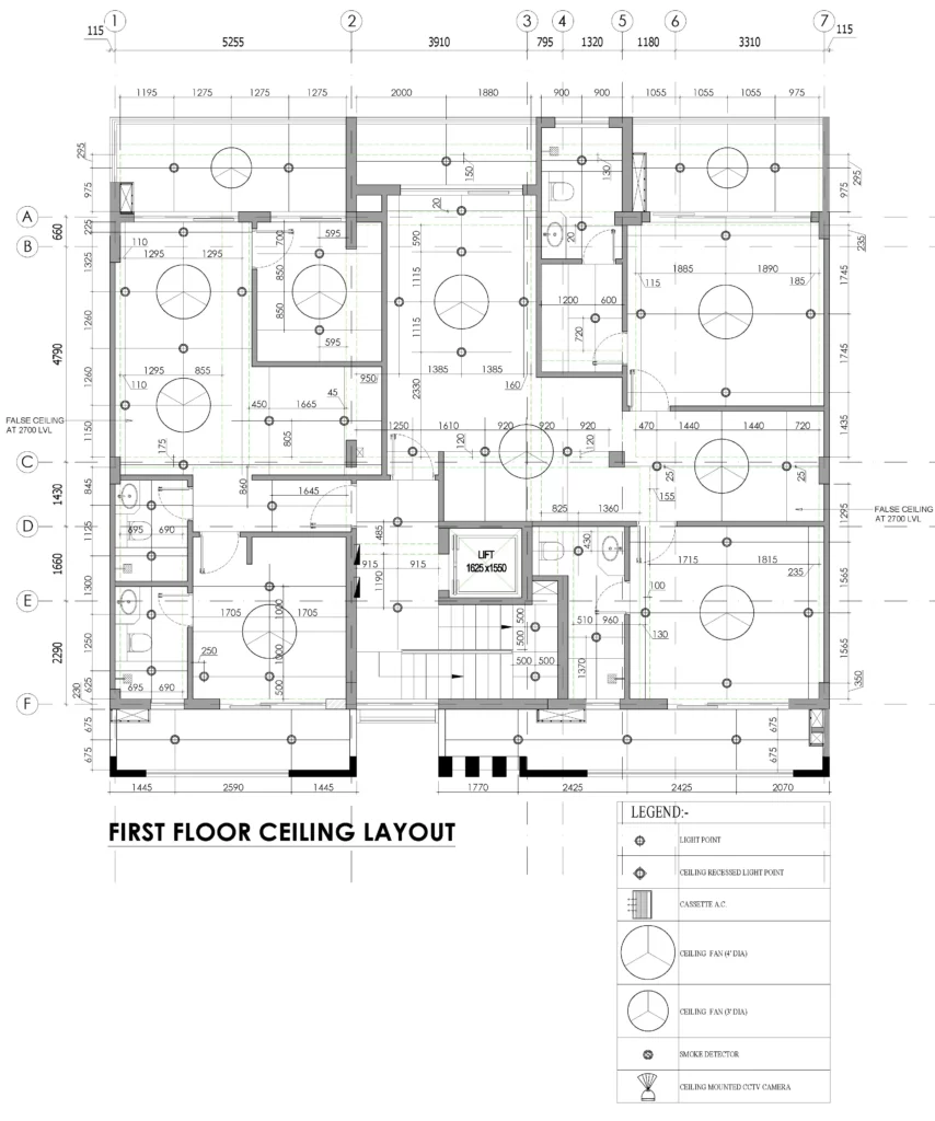
4) Electrical wiring layout of a residential building

Overall, planning an electrical installation requires careful attention to detail, adherence to electrical codes and regulations, and a thorough understanding of electrical components and systems. It is recommended to hire a qualified electrician or electrical engineer to design and install the system.
This post is very helpful and I would like to thank you in advance. In addition to this web can you share me any pdf document of this web or any related reference.