
If you want to know about the smoke movement in a building or general exit requirements or auditorium design, please click the link.
A stairwell pressurization system is a mechanical ventilation system designed to prevent the ingress of smoke into a building’s stairwells during a fire. In the event of a fire, the system works by creating a higher air pressure inside the stairwell compared to the surrounding areas. This higher air pressure helps to prevent the ingress of smoke from the fire into the stairwell, allowing building occupants to safely evacuate the building.
In a high-rise building, the stairs typically represent the sole means of egress during a fire. It is imperative for the exit stairs to be free of smoke and to incorporate design features that improve the speed of occupant egress. Most building codes require the fire stairwells in a high-rise building to be pressurized to keep smoke out.
The stairwell pressurization serves several purposes
- Inhibit migration of smoke to stairwells, areas of refuge, elevator shafts, or similar areas.
- Maintain a tenable environment in areas of refuge and means of egress during the time required for evacuation.
- Facilitate the fire and rescue operation by improving visibility in the building for the firefighting crew.
- Protect life and reduce damage to property.
Three specific means for providing smoke proof enclosures
- Naturally ventilated stair balconies
- Mechanical ventilation of a stair
- Stair pressurization
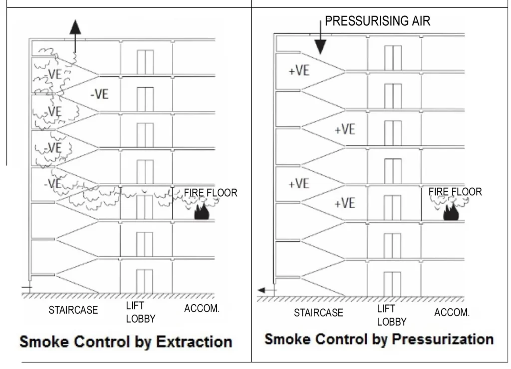
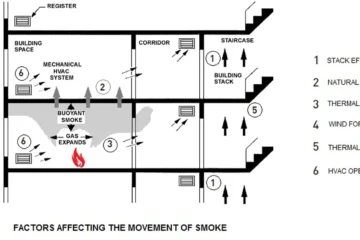
1) Smoke control methods
- The primary means of controlling smoke movement is by actively manipulating the pressure conditions in a way that fire gases are made to flow out from the building and prevent entry into the confined space.
- The work methods, the choice of them, and the tactical structure of the fire and rescue operation depend on the objective and purpose of the measures.
- Before we proceed, let’s define three important terms first
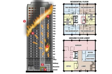
1. High-Rise Building: Any building greater than 75 feet in height, measured from the ground level access to the highest floor level intended for occupant use” is categorized as a high-rise building.
International Building Code (IBC) Section 403 also has a similar definition.
2. Smoke Refuge Area: An area of the building separated from other spaces by fire resistant rated smoke barriers, in which a tenable environment is maintained for the period of time that such areas might be occupied at the time of fire.
3. Tenable Environment: An environment in which smoke and heat are limited or otherwise restricted to maintain the impact on occupants to a level that is not life threatening. The principal objective of a smoke control system is to maintain a tenable environment longer than the required safe egress time.
Smoke control methods are often defined as active or passive systems.
- An active smoke control system uses mechanical equipment to control the spread of smoke in a structure. It includes pressurization method, airflow method and exhaust method.
- A passive smoke control system uses building construction materials to limit the spread of smoke in a structure. Typical passive smoke control systems include compartmentation, fire rated walls, barriers, smoke vents, shafts etc.
- The International Building Code (IBC) allows three active smoke control methods to contain smoke:
- Pressurization Method
- Airflow Design Method
- Exhaust Method
i) Pressurization Method
- Pressurization systems use mechanical fans to produce a positive pressure on the stairwells.
- The two key pressurization principles are maintaining:
- A pressure difference across a barrier
- Average velocity of sufficient magnitude.
- Consider an example of a stairwell “A” maintained at a positive pressure relative to lift lobby “B” which is at a higher pressure relative to the fire zone corridor space “C”. Each of the three zones A, B and C are separated by the partition barriers and the doors. The lobby and stairwell (marked green) can be classified as escape routes, refuge area and tenable environment. These invariably repeat themselves at the same position at each floor level for at least a number of successive floors.

- We learned that air flows from the higher pressure area to the lower pressure area.
- The principle of maintaining a tenable environment is to prevent migration of smoke laden air from zone “C” to zone “B” and to zone “A”.
- This is achieved by pressurizing the stairwell and lobby such that the pressure in zone A is greater than the pressure in zone B, which in turn is maintained greater than zone C.
ii) Airflow Velocity Method
- The airflow design method is typically used where large openings are created, for example, due to opening of doors across a fire barrier.
- It is difficult to sustain design pressures in such scenarios and under such situations; smoke will find its way to the refuge areas or escape routes.
- Airflow method employs air velocity to control smoke movement.
- The minimum average velocity through a fixed opening is estimated as.

Where:
- h = Height of opening, feet
- Tf = Temperature of smoke, °F
- To = Temperature of ambient air, °F
- v = Air velocity, feet per minute (fpm)
Caution
- A disadvantage of the airflow method is that it supplies large quantities of air which may unduly intensify the fire, disrupt plume dynamics or interfere with exiting systems.
- Therefore, airflow velocity towards the fire should NOT exceed 200 fpm. Where the equation above yields values over this limit, the airflow method shall not be used.
- A multi-level enclosed parking garage with openings at each level is an example of a place where an Airflow Design Method should be utilized.
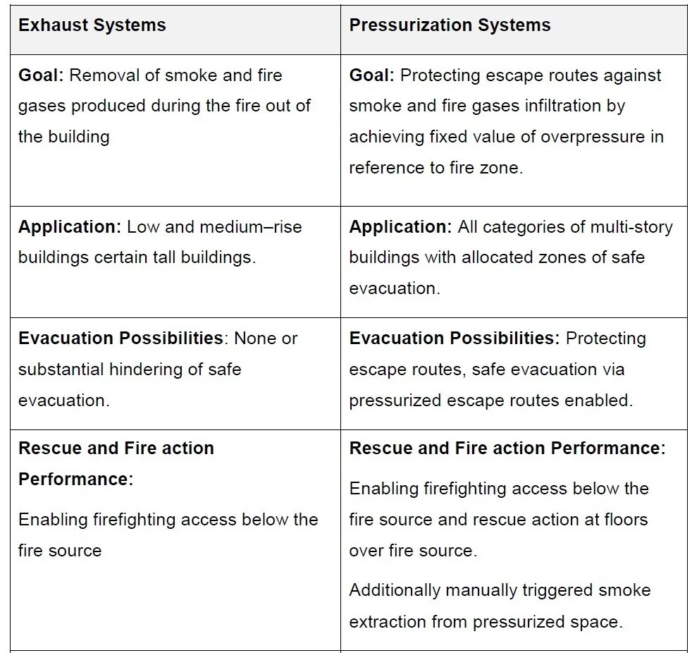
iii) Exhaust Method
- The exhaust method is generally utilized in large open spaces, such as covered malls and atriums.
- It provides negative pressure in the spaces through exhaust fans, and the design intent is to maintain the layer of smoke at least 10 feet above any walking surface.
- Airflow is calculated on the volume of the space and the make-up air fans supply outside air typically at 80% of the calculated volume of the exhaust.
- This method is unlike the pressurization system, which provides a slightly higher pressure in the escape routes such as stairwell.
- A comparison is tabulated below:
2) Performance issues and challenges
The design of stairwell pressurization systems gets complicated with regards to three scenarios:
1. Stack effect – Pressure stabilization is difficult to achieve in high-rise buildings. The phenomenon is more pronounced in tall buildings and in locations where there are wide variations in ambient temperatures. Designing a pressurized stairwell system especially in cold climate requires designer to consider the variables of temperature, wind and construction standards. Tight stairwell construction helps reduce the stack effect.
2. Inadequate vents – Satisfactory pressurization of a stairwell could be difficult during all closed-door conditions and a building with inadequate vents.
3. Evacuation time – Intermittent loss of effective pressurization occurs when occupants enter and leave stairs during evacuation. The exterior stairwell door is the greatest cause of pressure fluctuation, and it is important to conservatively take into account the number of doors that may be open simultaneously during an emergency. This number will depend largely on the building occupancy.
The high-rise building pressurization design becomes more complex and often requires additional analysis which may be performed with the use of analytical calculations, zone-models or CFD simulations that confirm effectiveness of selected solution.
3) System design
- The stairwell pressurization system is a mechanical ventilation system.
- In order to pressurize the stairs of vertical buildings, it is necessary to install sets of fans that suck air into the stairwell, keeping pressure of 0.10 – 0.45 inch water gauge.
- The main purpose is to prevent infiltration of smoke in the event of a fire.
- The system consists of the installation of a fan with an electric motor mounted in an isolated compartment. The outside air is captured through a shutter that has a particle filter.
- The excess air is relieved through manual and automatic dampers properly calculated and installed at the suitable locations.
4) Pressurization techniques
Stairwell smoke control employs one or more of these design techniques.
- Non-compensated pressurization
- Compensated pressurization
- Single injection pressurization
- Multiple injection pressurization
i) Non-compensated systems
- A non-compensated system provides a constant volume of air by a single-speed fan.
- The level of pressurization depends on the number of doors open.
- When access doors open, the pressure in the stairwell drops.
- When access doors close, the pressure rises.
- Non-compensated stairwell pressurization is reasonably well when:
- Stairwells are in a lightly populated building (for example: luxury apartments).
- Stairwell access doors are usually closed, but when used, remain open only for a few seconds.
ii) Compensated systems
- A compensated system adjusts to any combination of door openings by maintaining a positive pressure differential across the openings.
- Systems compensate for changing conditions by either modulating air flow or relieving excess pressure from the stairwell.
- A compensated pressurization system will have more components (sensors, relief dampers, VFDs, etc.) and control sequences.
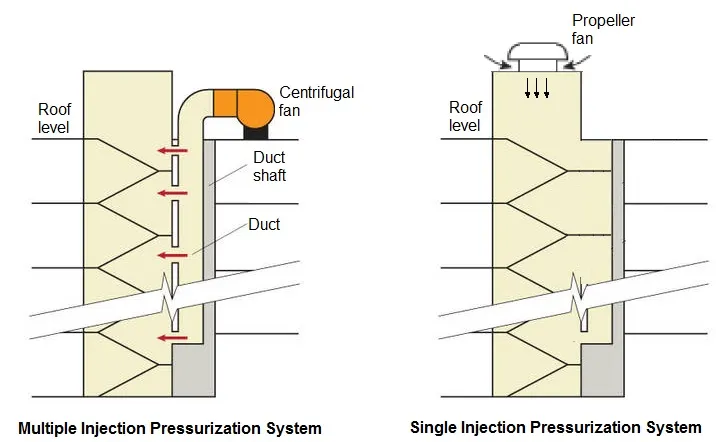
iii) Single Injection Pressurization
- A single injection system uses pressurization air at one location.
- While the strategy is simple, a single injection system can fail if a stairwell access door opens near the injection point.
- Loss of pressurization air will occur immediately at the access doors farther from the injection point.
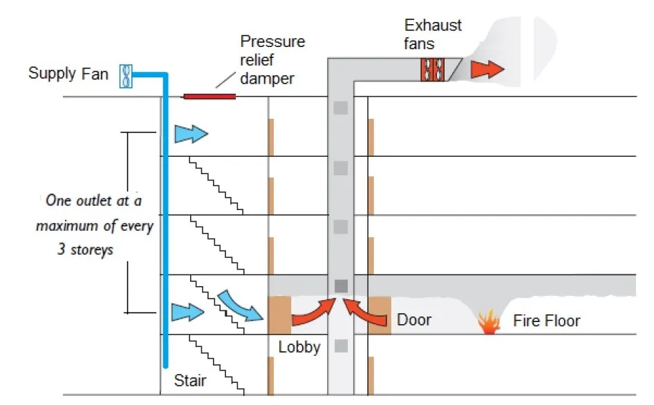
- The most common injection point is at the top of the building.
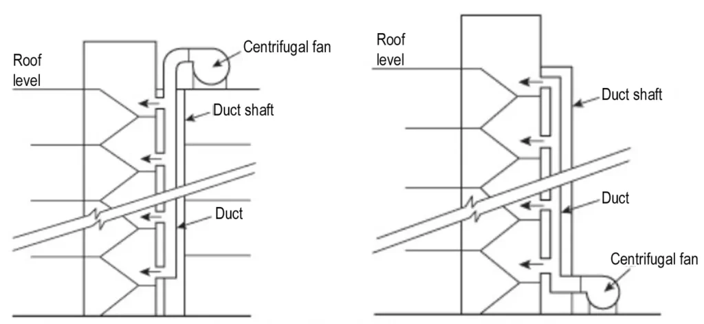

iv) Multiple Injection Pressurization
- The multiple injection technique supplies air from more than one location.
- The scheme may use multiple fans or a single fan connected to a ducted arrangement with multiple outlets.
- How far apart these air injection points should be located is dependent on the height of the building, and most guidelines suggest locating them at 3 to 5 floors apart.
5) System Design and Components
- A pressurization system consists of two main components
- Supply air (where air is injected into the area that is to be protected)
- Relief air (to avoid overpressure when doors are closed)
- The System comprises:
- Supply fans for introducing air.
- Distribution systems comprising ducting, terminal diffusers and venting arrangements.
- Automatic air release vents/dampers to release excess air and avoid over pressurization when doors are closed.
- Automatic control system comprising fire alarms, smoke detectors, safety switches and devices at locations to suit fire service.
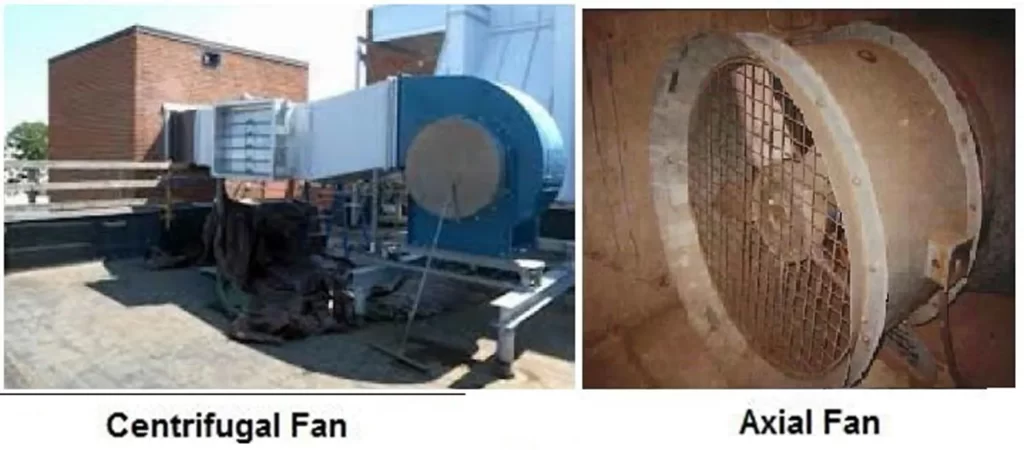
i) Supply Air Fans
- Supply air fans for pressurization are either the centrifugal or axial type. Centrifugal fans generate airflow in a radial direction to the impeller. Axial fans on the other hand, generate airflows parallel to the impeller.
- Both centrifugal and axial fans can provide adequate capacity and static pressure to overcome the resistance. Axial in-line fans are often preferred because:
- They have a relatively flat pressure curve with respect to varying flow. Therefore, as doors are opened and closed, the axial fans quickly respond to airflow changes without major pressure fluctuations.
- They are usually less costly and have lower installed costs.
- The drawback is that they are readily affected by wind pressure on the building. These often require windshields at the air intake, especially when they are wall-mounted. This is less critical when axial fans are mounted on roofs because they are often protected by parapets and the direction of the wind is at right angles to the axis of the fan.
- The pressurization fan may be activated manually or automatically by means of a fire detection system. An additional manual switch at the entrance gate of the building and on the electric fan panel may be required by many state codes. Check with applicable design standards and/or codes enforced by the authority having jurisdiction (AHJ).
ii) Fan Drive Package
The International Building Code (IBC) requires fans used for smoke control purposes:
- To operate at or below their rated horsepower and to be selected with a minimum service factor of 1.15.
- To have 1.5 times the number of belts required for design duty, and no fewer than two.
- To be designed to run in a stable portion of the fan curve. All fans have performance curves based on the airflow being provided and the static pressure present.
- To have an adequate capacity to deliver performance while operating in a stable portion of the fan curve.
- To operate at elevated temperatures.
iii) Location of Fans
- The stairwell pressurization fan can be located anywhere, but since the entry/exit doors at ground level will remain open during emergency for fire personnel entry as well refuge escape operations, the top location is preferred to avoid the short-circuiting of the air.
- Fans shall be positioned to avoid introducing smoke and toxic gases into the stair especially when located at high level.
- There should be two air intakes facing different directions in order not to be affected by the same source of smoke. Each air intake shall be protected by a smoke control damper operated independently via a smoke detector in such a way that if one damper closes due to smoke contamination, the other air intake will supply the air requirements of the system without interruption.
- The air intakes should be ducted to the fan inlet. This measure is necessary to prevent the pressurization fan reducing the pressure in the plant room below atmospheric pressure and hence inducing flow from the building towards the plant room.
- Each inlet shall be independently capable of providing the full air requirements of the system.
- The air intake shall not be less than 5m horizontally from any exhaust discharge opening and be independent from wind speed and direction.

Note – smoke detectors at the fan inlet are necessary to shut down the fan and close the inlet damper to prevent recirculation of smoke.
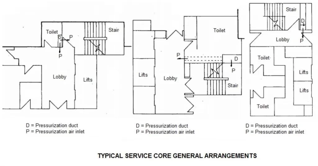
iv) Distribution arrangements
- For high-rise buildings the preferred distribution arrangement is a vertical duct running adjacent to the pressurized spaces.
- Distributing to these areas can be achieved by:
- A single fan serving a vertical duct with short horizontal branches to each floor.
- Multiple plants serving multiple floors.
v) Ductwork
- There is no real difference between supply air ductwork used for comfort HVAC and the pressurization air systems.
- The pressurization air can be delivered either from a dedicated galvanized duct work or a masonry shaft.
- Experience indicates that without sealing and internal lining of the surfaces, the masonry ducts have excessive friction loss and 20 to 50% air leakage.
vi) Motorized Smoke & Fire Dampers (MSFD)
Dampers for smoke control systems are required to meet UL 555S. This is consistent with those requirements found in NFPA 92. The IBC further regulates the type of smoke damper to be used. IBC requires:
- Smoke dampers to have leakage ratings no less than Class II and elevated temperature ratings of not less than 250°F. This limits the allowable leakage from the damper at the higher temperature expected in the system.
- The operating temperature shall be at least 50°F (10°C) above the maximum smoke control temperature or a maximum of 350°F (177°C). This is to ensure the damper will not close prematurely when the system is operating in the smoke control mode.
vii) Pressure Relief Venting
- Stairwell pressurization systems are accompanied with a vent system.
- The purpose of the vent is to relieve excess pressures in the stair when doors are opened and closed.
- When a door is opened, the pressure in the stair is reduced and the relief vent closes, thereby diverting the excess air to the open door. When the door closes, the vent serves as a relief for excess pressures in the stair to reduce door-opening forces.
- One of the following methods may be adopted to relieve excess air:
viii) Automatic Opening Door
- This is the simplest form of control.
- It uses electric unlocking of door in the event of high pressure in the stairwell.
- Under normal conditions, the exterior stairwell door would normally be locked for security reasons and open on fan activation.
ix) Barometric Dampers
- Barometric dampers use adjustable counterweights which are adjusted so that the damper opens when a particular (excessive) pressure is reached.
- The location of dampers needs to be carefully chosen since dampers located too close to the supply openings can operate too quickly.
x) Motor-Operated Dampers
- Motor-operated dampers use signals from a differential pressure sensor to actuate.
- These dampers may have pneumatic or electric motor actuators triggered by the pressure differential between the stair and floors served by the stair.
xi) Exhaust Fan
- An exhaust fan can be used to relieve excess pressure. The operation of fan is triggered by signals from a differential pressure sensor. The fan will shut off when the pressure difference falls below a specified level.
- The figure below illustrates various air relief concepts:
xii) Supply Fan Bypass
- When all the stairwell doors are closed, the pressure difference increases and the bypass damper opens in response to differential pressure readings, thereby increasing the bypass air and decreasing the supply air to the stairwell.
xiii) Variable Frequency Drive for the Fan
- The variable frequency drive (VFD) is becoming increasingly popular in modern pressurization systems.
- VFD allows the fan speed (RPM) to be altered thereby modulating the airflow.
- The control signal is obtained from a pressure sensor controller that senses the static differential pressure between the stairwell and the occupied zone and gives feedback for corrective action.
Stairwell pressurization systems are typically required by building codes in high-rise buildings, as they can significantly improve the safety of building occupants during a fire. They are often combined with other fire protection systems, such as sprinklers and fire alarms, to create a comprehensive fire protection strategy for the building.
Sir/Madam,
We would like to request a sequence of operations for the multiple injection systems with a variable frequency drive supply fans and supply by-pass damper with static pressure air controller.