If you want to know about the layout of substation in a building or concept of earthing system or introduction of electricity production, please click the link.
Designing a substation or switchroom requires careful planning and consideration of various factors to ensure the safety, reliability, and efficiency of the electrical system. Here are some guidelines to follow:
1) Location and other requirements
The location and other requirements of a substation and switch rooms shall be as given below.
i) Point No. – 1
- Availability of power lines nearby may be kept in view while deciding the location of the substation.
ii) Point No. – 2
- The substation should preferably be located in a separate utility building and may be adjacent to the generator room, if any.
- Location of substation in the basement should be avoided, as far as possible.
iii) Point No. – 3
- In case there is only one basement in a building, the substation/switch room shall not be provided in the basement.
- Also, the floor level of the substation shall not be lowest point of the basement.
iv) Point No. – 4
- Ideal location for an electrical substation for a group of buildings will be at the electrical load centre.
- Generally, the load centre will be somewhere between the geometrical centre and the air conditioning plant room, as air conditioning plant room will normally be the largest load, if the building(s) is centrally air conditioned.
v) Point No. – 5
- In order to prevent storm water entering the transformer and switch rooms through the soak-pits, the floor level of the substation/ switch room shall be at least 300 mm above the highest flood water level that may be anticipated in the locality.
- Also, facility shall be provided for automatic removal of water.
vi) Point No. – 6
- Substation shall not be located immediately above or below plumbing water tanks or sewage treatment plant (STP) water tanks at the same location.
vii) Point No. – 7
- All door openings from substation, electrical rooms, etc., should open outwards.
- Vertical shutters (like fire rated rolling shutters) may also be acceptable provided they are combined with a single leaf door opening outwards for exit in case of emergency.
- For large substation room/electrical room having multiple equipment, two or more doors shall be provided which shall be remotely located from each other.
viii) Point No. – 8
- If substation is located at a height 1000 m above MSL, then adequate derating of equipment shall be considered.
ix) Point No. – 9
- In case of HV panel and transformers located at different floors or at a distance more than 20 m, HV isolator shall be provided at transformer end.
x) Point No. – 10
- In case transformer and main MV/LV panel room are located at different floors or are at a distance more than 20 m, MV/LV isolator shall be provided at transformer end.
- In case transformer and main MV/LV panel room are located at different floors, the designer should also take care of the safety requirements caused by lack of direct visibility of the status of the controlling switch.
- To cater to the safety requirements under different conditions of operation as well as maintenance, it may be necessary to provide additional isolator or an emergency push button in the vicinity to trip the supply.
- Decision has to be taken based on the possible risks.
xi) Point No. – 11
- No services or ventilation shafts shall open into substation or switch room unless specific to substation or switch room.
xii) Point No. – 12 (Oil-filled installation)
- Substations with oil-filled equipment require great consideration for the fire detection, protection and suppression.
- Oil-filled transformers require a suitable soak pit with gravity flow to contain the oil in the event of the possibility of oil spillage from the transformer on its failure.
Installation of oil-filled equipment shall meet the following requirements
- Substations with oil-filled equipment / apparatus [transformers and high voltage panels] shall be either located in open or in a utility building. They shall not be located in any floor other than the ground floor or the first basement of a utility building. They shall not be located below first basement slab of utility building. They shall have direct access from outside the building for operation and maintenance of the equipment.
- Substations/Utility buildings (where the substation or oil-filled transformer is located) shall be separated from the adjoining buildings including the main building by at least 6 m clear distance to allow passage of fire tender between the substation/utility building and adjoining building/main building.
- There shall be no interconnecting basement with the main building underneath the oil-filled transformers.
- Provisions for oil drainage to a point at a lower level and separated by adequate fire barrier shall be provided. If there is a floor directly below the ground floor level or first basement where the oil-filled transformers and oil-filled circuit breakers are placed, then they shall be separated by a fire barrier of appropriate fire rating as per Fire and Life Safety and proper oil drainage system shall be provided to avoid possible leakage of oil into the lower floor.
- Substation equipment having more than 2000 litre of oil whether located indoors in the utility building or outdoors shall have baffle walls of 4h fire rating between apparatus.
- Provisions shall be made for suitable oil soak-pit, and where use of more than 9000 litre of oil in any one oil tank, receptacle or chamber is involved, provision shall be made for the draining away or removal of any oil which may leak or escape from the tank, receptacle or chamber containing the same. Special precautions shall be taken to prevent the spread of any fire resulting from the ignition of the oil from any cause and adequate provision shall be made for extinguishing any fire which may occur.
- In respect of all oil type transformers located at basement, a kerb (sill) of a suitable height shall be provided at the entrance in order to prevent the flow of oil from a ruptured transformer into other parts of the basement in the event of the possibility of oil spillage from the transformer on its failure.
- Adequate fire barriers or deflectors shall be provided to avoid flames from the substation reaching or affecting the upper floors (see also Fire and Life Safety).
- For transformers having large oil content (more than 2000 litre), Rule 44(2) of the Central Electricity Authority (Measures Relating to Safety and Electric Supply) Regulations, 2010 as amended from time- to-time shall apply (see Annex B).
xiii) Point No. – 13 (Dry-type installation)
- In case electric substation has to be located within the main multi-storeyed building itself for unavoidable reasons, it shall be a dry-type installation with very little combustible material, such as, a dry type of transformer with vacuum (or SF6) breakers as HT switchgear and ACB or MCCB as medium voltage (MV) switchgear.
- Such substations shall be located on the ground level or on first basement and shall have direct access from the outside of the building for operation and maintenance of the equipment.
- Exceptionally, in case of functional buildings, such as air traffic control towers, data centres and buildings of height more than 100 m having high electrical load requirement, dry-type installations/substations may also be provided at upper level.
- This measure will decrease the current flow and short-circuit rating at various points, thereby reducing vulnerability to fire.
- In such cases, a base substation shall be located at ground floor/first basement to cater to the main MV/LV panel which feeds life and safety services loads as defined in below (Power supply to emergency fire and life safety systems)
- The base substation shall be located in such a way to provide direct access to the firemen in case of any emergency.
- The power supply control to any substation or transformer located at upper floors shall be from the base substation so that in case of fire, the electrical supply can be easily disconnected to avoid additional losses.
xiv) Point No. – 14
- The power supply HV cables voltage shall not be more than 12 kV and a separate dedicated and fire compartmented shaft should be provided for carrying such high voltage cables to upper floors in a building.
- These shall not be mixed with any other shaft and suitable fire detection and suppression measures shall be provided throughout the length of the cable on each floor.
xv) Point No. – 15
- The provision for installation and removal of substation equipment should be provided from inside or outside the building without disturbing the associated major equipment in the substation.
xvi) Point No. – 16
- In case of compact substation, design and location of the substation shall ensure safety of the people around the compact substation installed along walkways, playgrounds, etc.
- Compact substation with incomer voltage of 12 kV or less, when located in open areas shall have fencing or barrier (of any metal-based protection, such as wire mesh or chain link, which is duly earthed) against unauthorized contact possibility around it at a minimum distance of 750 mm around it with access for maintenance from all four sides.
- For incomer voltage more than 12 kV and less than 24 kV the fencing distance from substation may be 1000 mm minimum.
- In case of more than 24 kV incomer, the distance may be further increased accordingly.
- The fencing design should take care of the servicing and maintenance requirements of the substation equipment.
xvii) Point No. – 17
- In case of two transformers (dry type or transformers with oil quantity less than 2000 litre) located next to each other without intermittent wall, the distance between the two shall be minimum 1500 mm for 11 kV, minimum 2000 mm for 22 kV and minimum 2500 mm for 33 kV.
- Beyond 33 kV, two transformers shall be separated by baffle wall of 4h fire rating.
xviii) Point No. – 18
- Horizontal routing of HT cable through functional / occupied areas should be avoided in view of safety.
xix) Point No. – 19
- If dry type transformer is used, it may be located adjacent to medium voltage switchgear in the form of unit type substation.
- In such a case, no separate room or fire barrier for the transformer is required either between transformers or between transformer and the switchgear, thereby decreasing the room space requirement; however, minimum distances as specified in above (Point No. – 17) shall be maintained between the apparatus depending upon voltage ratings.
- Layout of equipment should take care of the need that any one piece of equipment or sub-assembly can be taken out of service and out of the installed location, while keeping the remaining system in service.
- Working space for access for maintenance of equipment, while keeping an adjoining section of the substation live to maintain power supply to essential loads, may require additional space between such sections of equipment.
xx) Point No. – 20
- In places where flooding can occur and water level may go above 1000 mm, the base substation may be located on one level above the ground level of a utility building.
- In such cases, one feeder should feed ground level and levels below with automatic tripping of the feeder to avoid electrocution in case of live electricity coming in contact with water.
- Designers shall use their discretion in special cases and depending on the degree of reliability, redundancy and the category of load and make suitable provisions.
Note – In cases, where the substation is located one level above ground level of utility building, this should be after due evaluation of the other risks posed by such a location combined with the concurrence for such a decision from State Electricity Authority comprising the electrical inspectorate and the distribution licensee and the fire service.
xxi) Point No. – 21
- For acoustical enclosures/treatment, reference may be made to Acoustics, Sound Insulation and Noise Control.
xxii) Point No. – 22
- The minimum recommended spacing between the walls and the transformer periphery from the point of proper ventilation shall be in accordance with good practice (see also Figure below).
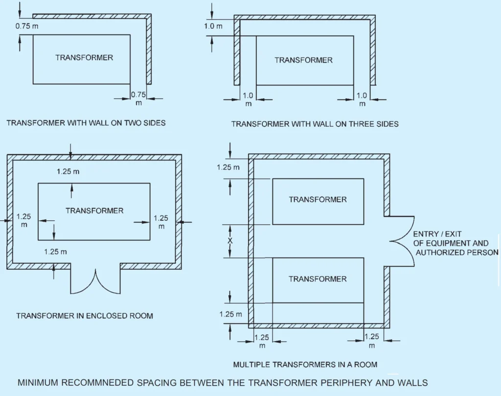
- The actual spacing may be different than those given in the figure, depending on the circumstances, such as access to the accessories.
- Other requirements relating to installation of transformers shall also be in accordance with good practice.
xxiii) Point No. – 23 (High voltage switch room/space)
- The design should take care of HV equipment space and clearance required around for maintenance and personnel safety as given in this link click here

- This room may preferably have direct access from outside.
- In case of substation having one transformer and one source of supply, the owner shall provide one high voltage switch.
- In case of single point supply with two or more transformers, the number of switch required will be one for incoming supply and one for each transformer.
- Additional space may be provided keeping in mind future requirement, if any. In case of duplicate supply, two switches shall be provided with mechanical/electrical interlocking arrangement.
- In case the number of incoming and outgoing switches exceed five, bus coupler of suitable capacity should invariably be provided.
xxiv) Point No. – 24 (Medium voltage switch room/space)
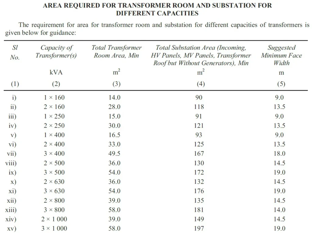
- The floor area required in respect of medium voltage switchgear room may be determined keeping in view the number and type of incoming/outgoing bus coupler switches including likely expansion in future and space requirement as given in this link click here

- The additional requirements of MV switchroom when located separate from the substation shall be as per in this link click here
xxv) Point No. – 25
- Other requirements relating to installation of switchgears and control gears as given in good practice shall also be complied with.
xxvi) Point No. – 26
- The minimum height of substation room/HV switch room/MV switch room shall be arrived at considering 1200 mm clearance requirement from top of the equipment to the below of the soffit of the beam (see also figure below).
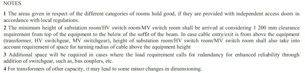
- In case cable entry/exit is from above the equipment (transformer, HV switchgear, MV switchgear), height of substation room/HV switch room/MV switch room shall also take into account requirement of space for turning radius of cable above the equipment height.
xxvii) Point No. – 27
- All the rooms shall be provided with partitions up to the ceiling and shall have proper ventilation.
- Special care should be taken to dissipate transformer heat and where necessary fresh air louvers at lower level and exhaust fans at higher level shall be provided at suitable locations.
xxviii) Point No. – 28
- In case of cable trench in substation/HV switch room/MV switch room, the same shall be adequately drained to ensure no water is stagnated at any time with live cables.
xxix) Point No. – 29 (Power supply to emergency fire and life safety systems)
- Emergency power supplying distribution system for critical requirement for functioning of fire and life safety system and equipment, shall be planned for efficient and reliable power and control supply to the following systems and equipment where provided:
- Fire pumps.
- Pressurization and smoke venting; including its ancillary systems such as dampers and actuators.
- Fireman’s lifts (including all lifts).
- Exit signage lighting.
- Emergency lighting.
- Fire alarm system.
- Public address (PA) system (relating to emergency voice evacuation and annunciation).
- Magnetic doors hold open devices; and
- Lighting in fire command centre and security room.
- Power supply to these systems and equipment shall be from normal and emergency (standby generator) power sources with change over facility.
- It shall be ensured that in case the power supply is from HT source/HT generation, transformers should be planned in stand-by capacity to ensure continuity of power to such systems.
- Wherever transformers are installed at higher levels in buildings and backup DG sets are of higher voltage rating, then dual redundant cables shall be taken to all transformers.
- The generator shall be capable of taking starting current of all the fire and life safety systems and equipment as above.
- Where parallel HV/LV supply from a separate substation fed from different grid is provided with appropriate transformer for emergency, the provision of generator may be waived in consultation with the Authority.
- The power supply to the panel/distribution board of these fire and life safety systems shall be through fire proof enclosures or circuit integrity cables or through alternate route in the adjoining fire compartment to ensure that supply of power is reliable to these systems and equipment. It is to be ensured that the cabling from the adjoining fire compartment is to be protected within the compartment of vulnerability.
- The location of the panel/ distribution board feeding the fire and life safety system shall be in fire safe zone ensuring supply of power to these systems.
- Cables for fire alarm and PA system shall be laid in metal conduits or armoured to provide physical segregation from the power cables.
xxx) Point No. – 30
- Other requirements as given in Central Electricity Authority (Measures relating to Safety and Electricity Supply) Regulations, 2010 as amended shall also be complied with.
- The fire safety requirements for substation and electrical rooms, including fire rating requirements of substations enclosure, that is, walls, floor, ceiling, openings, doors, etc., as given in Fire and Life Safety shall also be complied with.
By following these guidelines, you can ensure the safe, reliable, and efficient operation of your substation or switchroom.