
If you want to know about the planning of electrical installation or concept of earthing system or introduction of electricity production, please click the link.
Electrical fittings and accessories refer to a wide range of components used to connect, protect, and enhance electrical systems. These components include everything from switches, outlets, and light fixtures to circuit breakers, fuses, and surge protectors. Here are some common electrical fittings and accessories:
Get to know about switches & sockets and other things. Every kind of electrical fittings for every kind of building.
1) Ceiling Roses and Similar Attachments
Ceiling roses are decorative elements that are mounted on the ceiling and used to hide the wiring connections of a pendant light fitting. They are typically made of plastic or metal, and come in a variety of shapes, sizes, and designs to match the décor of the room.
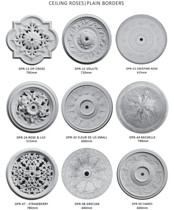
Ceiling roses serve both a functional and aesthetic purpose. They provide a neat and tidy way to cover the wiring connections of the light fitting, and also provide a decorative element that can enhance the overall look of the room.
Additionally, ceiling roses can add a touch of elegance and sophistication to a room, particularly if they are ornate or made from high-quality materials.
- A ceiling rose or any other similar attachment shall not be used on a circuit the voltage of which normally exceeds 250 V.
- Normally, only one flexible cord shall be attached to a ceiling rose.
- Specially designed ceiling roses shall be used for multiple pendants.
- A ceiling rose shall not embody fuse terminal as an integral part of it.
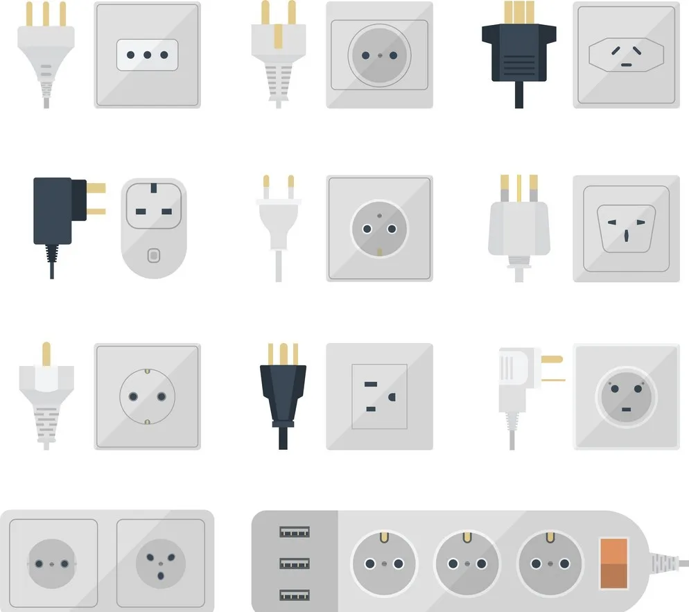
2) Socket-Outlets and Plugs
Socket-outlets and plugs are electrical components that are used to connect electrical devices to a power supply. Socket-outlets are mounted on the wall and provide a connection point for plugs, while plugs are attached to the end of electrical cords and are inserted into the socket-outlet to draw power.
- Each 16 A socket-outlet provided in buildings for the use of domestic appliances, such as, air conditioner and water cooler shall be provided with its own individual fuse, with suitable discrimination with back-up fuse or miniature circuit-breaker provided in the distribution/ sub distribution board.
- The socket-outlet shall not necessarily embody the fuse as an integral part of it.
- Each socket-outlet shall also be controlled by a switch which shall preferably be located immediately adjacent thereto or combined therewith.
- The switch controlling the socket-outlet shall be on the live side of the line.
- Ordinary socket-outlet may be fixed at any convenient place at a height above 200 mm from the floor level and shall be away from danger of mechanical injury.
Note – 1
- In situations where a socket-outlet is accessible to children, it is necessary to install an interlocked plug and socket or alternatively a socket-outlet which automatically gets screened by the withdrawal of plug.
- In industrial premises socket-outlet of rating 20 A and above shall preferably be provided with interlocked type switch.
- In case of public buildings, to facilitate operation of switches/socket-outlets by persons with disabilities and the elderly, these shall be installed at an accessible height for reaching and operating, between 800 mm and 1100 mm above floor level and shall be located at a minimum of 600 mm with a preference of minimum 700 mm, from any internal corner.
- They shall be so fixed so as to be away from danger of mechanical injury.
- As an exception, electrical wall socket outlets, telephone points and TV sockets can be located at a minimum height of 400 mm above floor level.
- In an earthed system of supply, a socket-outlet with plug shall be of three-pin or five-pin type with the third or fifth terminal connected to the earth.
- When such socket-outlets with plugs are connected to any current consuming device of metal or any non-insulating material or both, conductors connecting such current-consuming devices shall be of flexible cord with an earthing core and the earthing core shall be secured by connecting between the earth terminal of plug and the body of current-consuming devices.
- In industrial premises three-phase and neutral socket- outlets shall be provided with an earth terminal either of pin type or scrapping type in addition to the main pins required for the purpose.
- In wiring installations for residential buildings, metal clad switch, socket-outlet and plugs shall be used for power wiring.
- For industrial and commercial application socket outlets conforming to accepted standards with suitable circuit breakers shall be used.
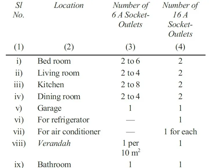
Note – A recommended schedule of socket-outlets in a residential building is given below.
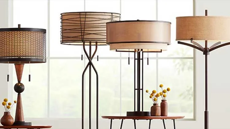
3) Lighting Fittings
Light fixtures are used to hold and connect light bulbs to the electrical system. They come in different types, including ceiling-mounted fixtures, wall-mounted fixtures, and table lamps.
- A switch shall be provided for control of every lighting fitting or a group of lighting fittings. Where control at more than one point is necessary as many two way or intermediate switches may be provided as there are control points. See also above lines.
- In industrial premises, lighting fittings shall be supported by suitable pipe/conduits, brackets fabricated from structural steel, steel chains or similar materials depending upon the type and weight of the fittings.
- Where a lighting fitting is supported by one or more flexible cords, the maximum weight to which the twin flexible cords may be subjected shall be as follows:

- No flammable shade shall form a part of lighting fittings unless such shade is well protected against all risks of fire. Celluloid shade or lighting fittings shall not be used under any circumstances.
- General and safety requirements for electrical lighting fittings shall be in accordance with good practice.
- The lighting fittings shall conform to accepted standards.
4) Fitting-Wire
Fitting-wire is a type of electrical wire that is used to connect electrical components and devices. It is also commonly referred to as hook-up wire or lead wire. Fitting-wire is typically made of copper or aluminum and is covered with an insulating material to protect against electrical shock and damage.

Fitting-wire is commonly used in a variety of applications, including in the construction of electrical circuits and devices, as well as in automotive, marine, and aviation applications. It can be used to connect electrical components such as switches, relays, and sensors, as well as to provide power to motors, lights, and other devices.
- The use of fitting-wire shall be restricted to the internal wiring of the lighting fittings.
- Where fitting-wire is used for wiring fittings, the sub-circuit loads shall terminate in a ceiling rose or box with connectors from which they shall be carried into the fittings.
5) Lamp holders
Lamp holders, also known as light sockets, are electrical devices that are used to hold and connect a light bulb to an electrical circuit. They are typically made of materials such as plastic, ceramic, or metal, and are available in a variety of shapes and sizes to accommodate different types of light bulbs.

- Lamp holders for use on brackets and the like shall be in accordance with accepted standards and all those for use with flexible pendants shall be provided with cord grips.
- All lamp holders shall be provided with shade carriers. Where centre-contact Edison screw lamp holders are used, the outer or screw contacts shall be connected to the “middle wire”, the neutral, the earthed conductor of the circuit.
6) Outdoor Lamps
Outdoor lamps are lighting fixtures designed for use outside of buildings, often in areas such as gardens, patios, and pathways. They come in a variety of styles and sizes to suit different applications, and can be made from materials such as metal, plastic, or glass.
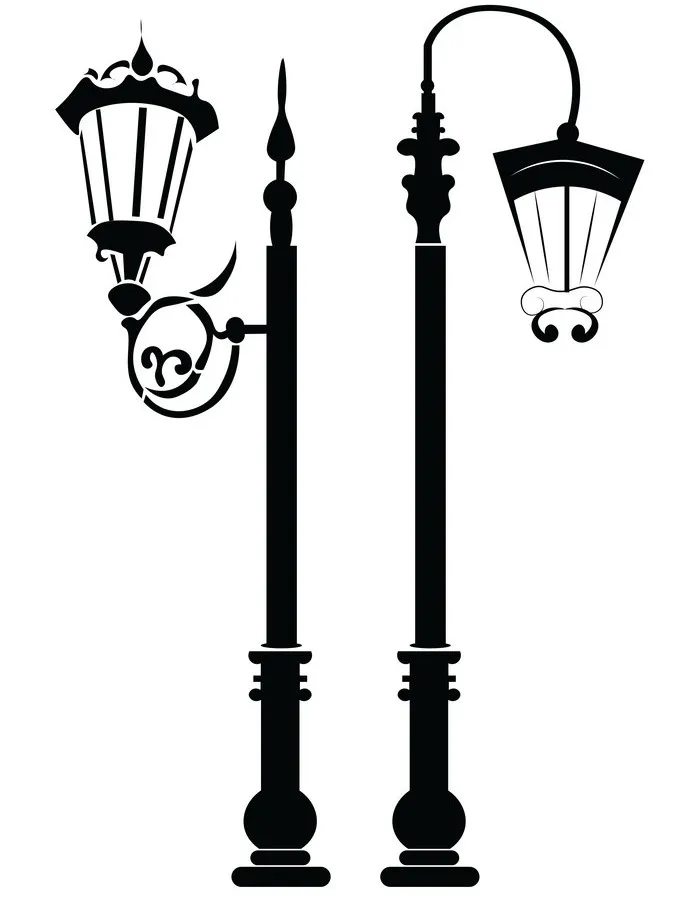
- External and road lamps shall have weatherproof fittings of approved design so as to effectively prevent the ingress of moisture and dust.
- Flexible cord and cord grip lamp holders shall not be used where exposed to weather.
- In verandahs and similar exposed situations where pendants are used, these shall be of fixed rod type.
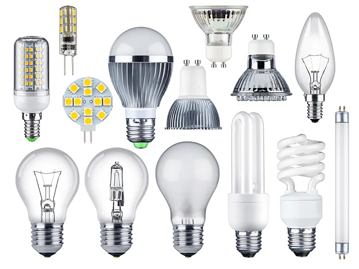
7) Lamps
Lamps are devices that produce light by converting electrical energy into electromagnetic radiation in the visible spectrum. They come in a variety of shapes, sizes, and styles, and can be used for a variety of purposes such as general lighting, task lighting, and accent lighting.
- All lamps unless otherwise required and suitably protected, shall be hung at a height of not less than 2.5 m above the floor level.
- All electric lamps and accessories shall conform to accepted standards.
Following shall also be ensured
- Portable lamps shall be wired with flexible cord. Hand lamps shall be equipped with a handle of moulded composition or other material approved for the purpose. Hand lamps shall be equipped with a substantial guard attached to the lamp holder or handle. Metallic guards shall be earthed suitably.
- A bushing or the equivalent shall be provided where flexible cord enters the base or stem of portable lamp. The bushing shall be of insulating material unless a jacketed type of cord is used.
- All wiring shall be free from short circuits and shall be tested for these defects prior to being connected to the circuit.
- Exposed live parts within porcelain fixtures shall be suitably recessed and so located as to make it improbable that wires will come in contact with them. There shall be a spacing of at least 125 mm between live parts and the mounting plane of the fixture.
8) Fans, Regulators and Clamps
i) Ceiling Fans
- Ceiling fans including their suspension shall conform to accepted standards and to the following requirements: Control of a ceiling fan shall be through its own regulator as well as a switch in series. See also above paragraph.
- All ceiling fans shall be wired with normal wiring to ceiling roses or to special connector boxes to which fan rod wires shall be connected and suspended from hooks or shackles with insulators between hooks and suspension rods. There shall be no joint in the suspension rod, but if joints are unavoidable then such joints shall be screwed to special couplers of 50 mm minimum length and both ends of the pipes shall touch together within the couplers and shall in addition be secured by means of split pins; alternatively, the two pipes may be welded. The suspension rod shall be of adequate strength to withstand the dead and impact forces imposed on it. Suspension rods should preferably be procured along with the fan.
- Fan clamps shall be of suitable design according to the nature of construction of ceiling on which these clamps are to be fitted. In all cases fan clamps shall be fabricated from new metal of suitable sizes and they shall be as close fitting as possible. Fan clamps for reinforced concrete roofs shall be buried with the casting and due care shall be taken that they shall serve the purpose. Fan clamps for wooden beams, shall be of suitable flat iron fixed on two sides of the beam and according to the size and section of the beam one or two mild steel bolts passing through the beam shall hold both flat irons together. Fan clamps for steel joist shall be fabricated from flat iron to fit rigidly to the bottom flange of the beam. Care shall be taken during fabrication that the metal does not crack while hammer to shape. Other fan clamps shall be made to suit the position, but in all cases, care shall be taken to see that they are rigid and safe.
- Canopies on top and bottom of suspension rods shall effectively conceal suspensions and connections to fan motors, respectively.
- The lead-in-wire shall be of nominal cross- sectional area not less than 1.5 mm2 copper and shall be protected from abrasion.
- Unless otherwise specified, the clearance between the bottom most point of the ceiling fan and the floor shall be not less than 2.4 m. The minimum clearance between the ceiling and the plane of the blades shall be not less than 300 mm. A typical arrangement of a fan clamp is given in Figure below.
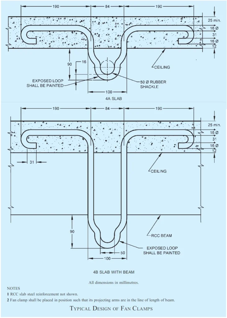
Note – All fan clamps shall be so fabricated that fans revolve steadily.
ii) Exhaust Fans
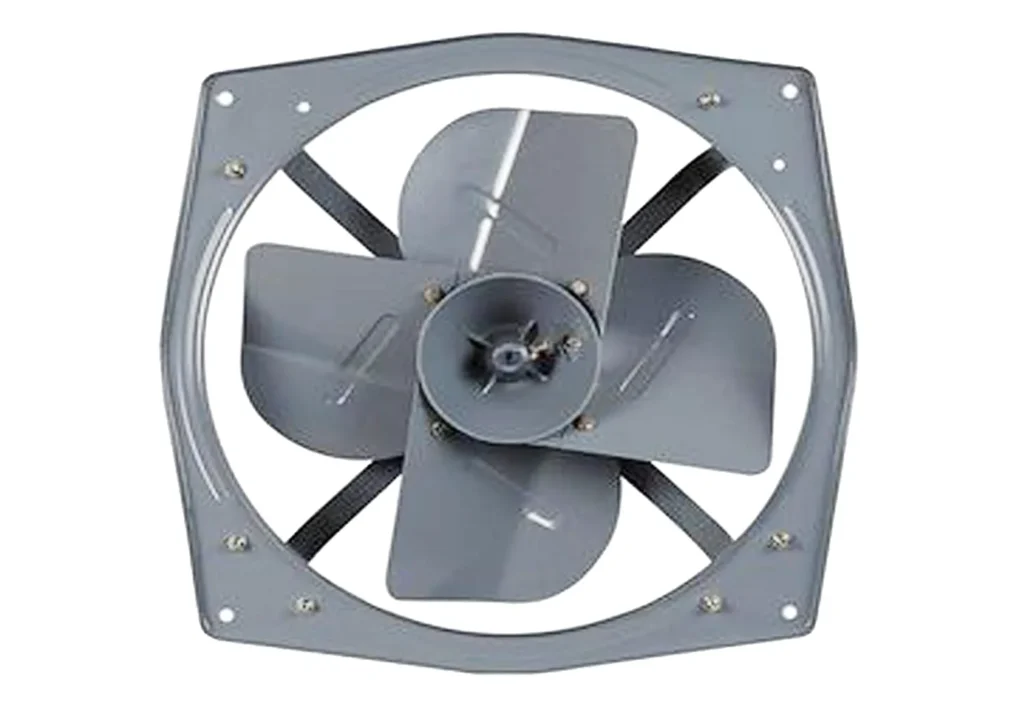
- For fixing of an exhaust fan, a circular hole shall be provided in the wall to suit the size of the frame which shall be fixed by means of rag-bolts embedded in the wall.
- The hole shall be nearly plastered with cement and brought to the original finish of the wall.
- The exhaust fan shall be connected to exhaust fan point which shall be wired as near to the hole as possible by means of a flexible cord, care being taken that the blades rotate in the proper direction.
iii) Fann age
- Where ceiling fans are provided, the bay sizes of a building, which control fan point locations, play an important part.
- Fans of 1200/1400 mm sweep normally cover an area of 9 m2 to 10 m2 and therefore in general purpose office buildings, for every part of a bay to be served by the ceiling fans, it is necessary that the bays shall be so designed that full number of fans can be suitably located for the bay, otherwise it will result in ill-ventilated pockets. In general, fans in long halls may be spaced at 3 m in both the directions.
- If building modules do not lend themselves for proper positioning of the required number of ceiling fans, other fans such as, air circulators or bracket fans will have to be employed for the areas uncovered by the ceiling fans.
- For this, suitable electrical outlets shall be provided although result will be disproportionate to cost on account of fans.
- Proper air circulation may be achieved either by larger number of smaller fans or smaller number of larger fans.
- The economics of the system as a whole should be a guiding factor in choosing the number and type of fans and their locations.
- Exhaust fans are necessary for spaces, such as community toilets, kitchens and canteens, and Godowns to provide the required number of air changes. Since the exhaust fans are located generally on the outer walls of a room, appropriate openings in such walls shall be provided for, in the planning stage.
Note – Exhaust fan requirement is based on the recommended air changes
9) Attachment of Fittings and Accessories
- In wiring other than conduit wiring, all ceiling roses, brackets, pendants and accessories attached to walls or ceilings shall be mounted on substantial teak wood blocks twice varnished after all fixing holes are made in them. Blocks shall not be less than 40 mm deep. Brass screws shall only be used for attaching fittings and accessories to their base blocks.
- Where teak or hardwood boards are used for mounting switches, regulators, etc., these boards shall be well varnished with pure shellac on all four sides (both inside and outside), irrespective of being painted to match the surroundings. The size of such boards shall depend on the number of accessories that can be conveniently and neatly be arranged. Where there is danger of attack by white ants, the boards shall be treated with suitable anti-termite compound and painted on both sides.
- Interchangeability Similar parts of all switches, lamp holders, distribution fuse-boards, ceiling roses, brackets, pendants, fans and all other fittings shall be so chosen that they are of the same type and interchangeable in each installation.
- Equipment Electrical equipment which forms integral part of wiring installations shall conform to the relevant Indian Standards, wherever they exist.
- Positioning of fans and light fittings shall be chosen to make these effective without causing shadows and stroboscopic effect on the working planes.
These are just a few examples of the many different electrical fittings and accessories that are available. It is important to choose the right components for your specific electrical system to ensure safety and reliability.
Need fitting and accessories for my house
Where is your location and what types of fitting and accessories do you need
So educational