If you want to know about the making of good for construction drawing or circulation in architecture or general building requirements, please click the link.
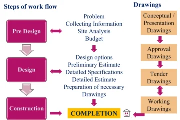
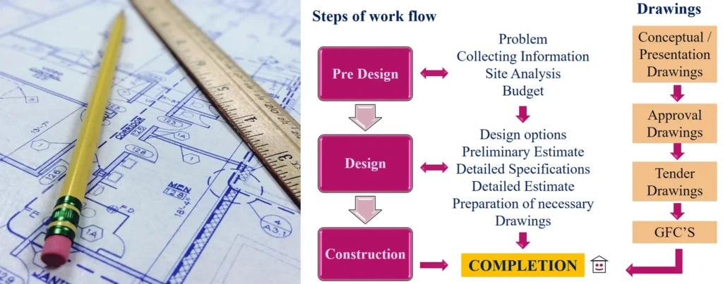
Construction drawings are essential documents that communicate design intent, building materials, and construction methods to contractors, engineers, and other professionals involved in the construction process.
1) Working drawing
A comprehensive set of drawings used in a building construction project which will include not only architect’s drawings but structural and services engineer’s drawings etc. is known as architectural working drawing.
2) Good for construction or working drawings
A good construction drawing is a critical aspect of the construction process. It provides a clear visual representation of the project, which is necessary for everyone involved in the construction, including architects, engineers, contractors, and subcontractors.
- A drawing helpful in construction of a building
- A technical drawing used as a guide for the construction team
Need of working drawings
- Communicate technical information
- Guide the contractor and construction team
- For good specification writing
- Reference for supervision
- Actual measurements of construction process
Working drawings vs Presentation drawings
Working drawings
- For construction
- For contractor
- Technical drawing
- Construction information
- Schedules and detailed drawings
Presentation drawings
- For presentation
- For customer and officials
- Artistic drawing
- Functional and aesthetical information
- Overall basic information drawings
3) Architectural working drawing
Architectural working drawings are technical drawings that provide detailed information on the design and construction of a building. These drawings typically include:
- Foundation plans
- Floor plans
- Sections
- Elevations
- Roof plan
- Site plan
- Reflected ceiling plan
- Typical details
- Schedules
Other drawings
- Electrical services layout
- Plumbing services layout
- Other services if required
The purpose of these drawings is to communicate the design intent, building code requirements, and construction details to all parties involved in the construction process.
4) How to prepare good drawings
Here are some tips to prepare good architectural drawings:
- Accurately drawn
- Properly dimensioned
- Properly represented
- Referring building codes
- Properly titled
- On appropriate scale
- Neatly arranged and understandable
- Full of necessary information
By following these steps, you can prepare accurate, clear, and concise architectural working drawings that effectively communicate your design intent to all parties involved in the construction process.
5) Preparation of working drawings
i) Create title box, title page and other important components
Title box
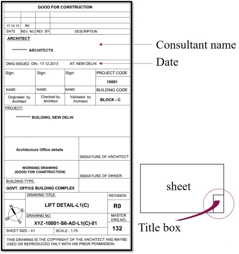
- Consultant name
- Other consultants
- Kind of project
- Name of owner
- Address of site
- Information about designer
- Draftsmen
- Person in charge
- Drawing title
- Drawing type
- Paper size
- Date
- Scale
Title page
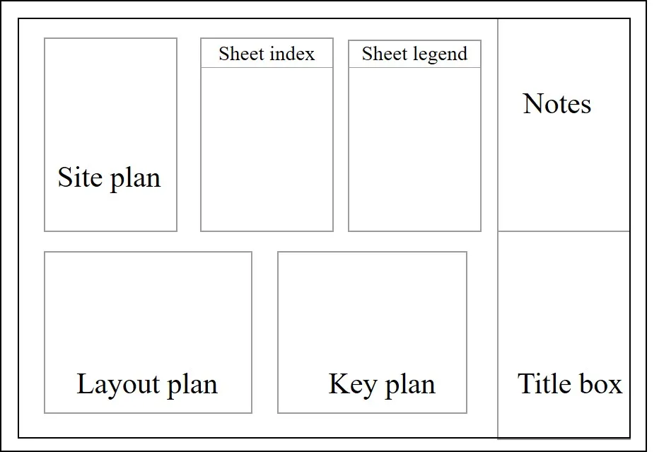
Other sheets

Other important components
- Lettering
- Symbols
- Abbreviations
- Scale
- Lines and drafting
- Dimensions
- Notes
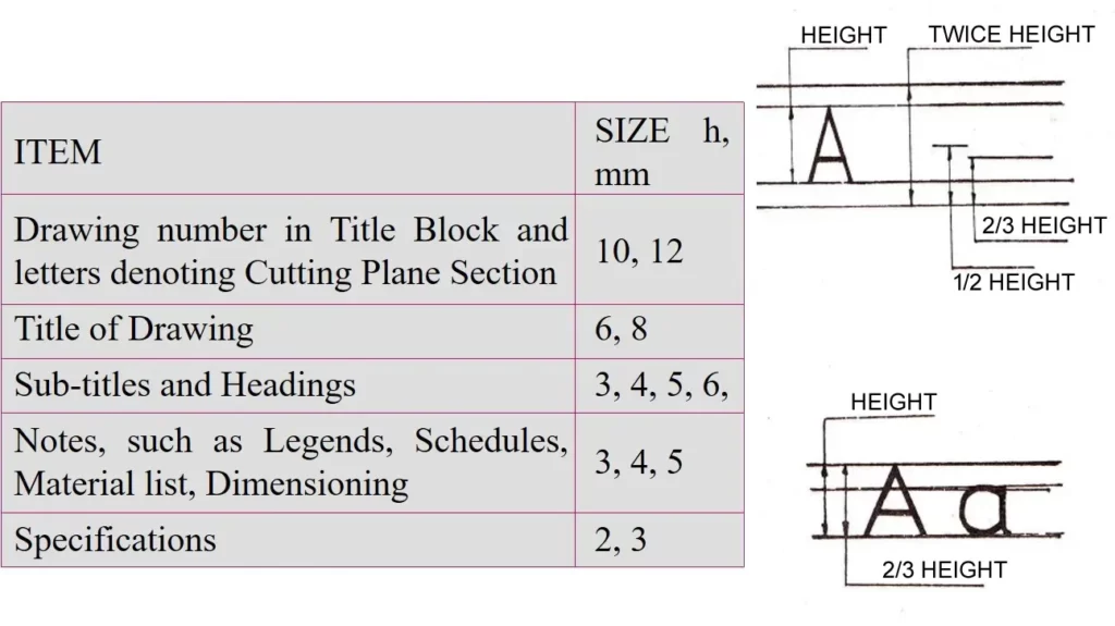
Lettering
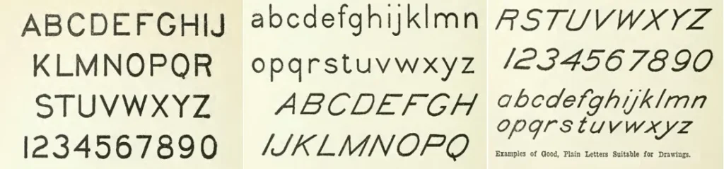
- Lettering can enhance a drawing by making it simple to interpret and easy to understand.
- In hand lettering we must, adaptable to the allotted space and to the impact for our lettering.
- A title should carry more weight than one small note that defines one small detail of construction.
- Sheet titles that cover large varieties of drawings, need a different type of lettering, perhaps smaller in size but with bolder stroke.
- There should be complementary relationship between drawing and lettering, so they properly reflect the information without one distracting from another.
Symbols and abbreviations
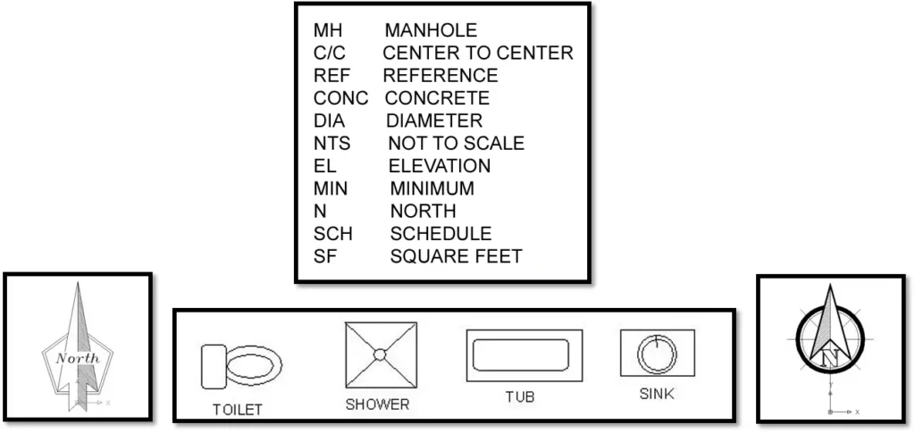
- Symbols and abbreviations used on drawings must be commonly known, defined in a legend attached to them or explained by note.
Scale
- Scaling in architectural work is vital. All drawings with few exceptions (isometric details) should be drawn to scale.
- To show the more drawings on the sheet, smaller scale should be used.
- For example, a large building plan which depicts a building is done on small scale, at the same time, details are shown at larger scale.
Lines and drafting
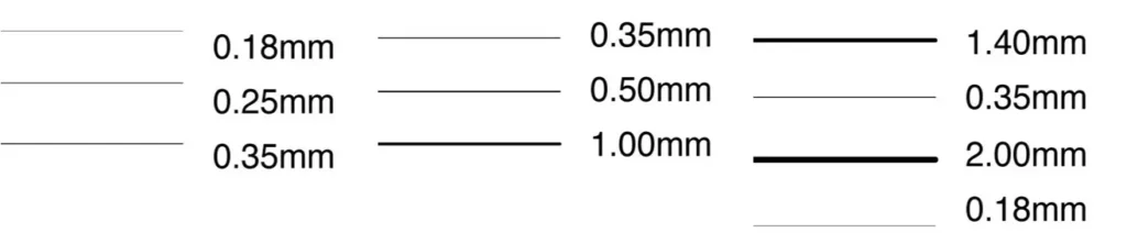
- Lines are the most expressive aspects of working drawings. Every line drawn should have some significance.
- If a line has little importance, it should be light, or if a line makes an important contribution to the drawing, it should be heavy and perhaps broad.
- Monotone drafting has no place in the architectural working drawing.
- Line variation and line contrast of lines, contribute directly to the success of drawings.
ii) Create floor plan
A floor plan is a two-dimensional representation of a building that shows the layout of each floor. Floor plans typically include:
- Room dimensions: The size and shape of each room or space on the floor.
- Doors and windows: The location, size, and type of doors and windows in each room or space.
- Wall thicknesses: The thickness of walls, which can help to indicate the type of construction used.
- Furniture and fixtures: The placement of furniture and fixtures, such as cabinets, toilets, and sinks.
- Electrical and plumbing systems: The location of electrical outlets, switches, and lights, as well as the location of plumbing fixtures, such as toilets and sinks.
- Structural elements: The location of structural elements, such as beams and columns, that support the building.
- Scale: A floor plan is typically drawn at a specific scale, which allows for accurate representation of the building’s size and layout.
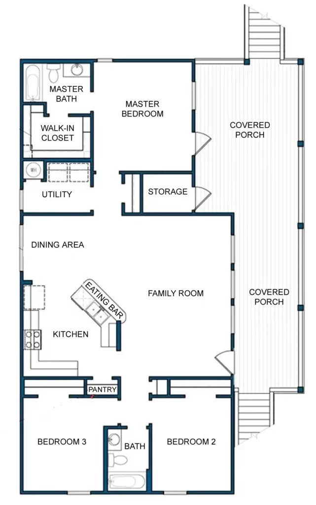
The floor plan is an essential component of the architectural working drawings, as it provides a clear understanding of the building’s layout and how the different spaces are organized and related to each other.
Importance of Plan
To determine the architectural concept of the building by showing.
- Different spaces, shapes and their relationships.
- Door and window places.
- Types of finishing materials.
- Entrances.
- Services like staircase, toilets, lifts, etc.
To show construction system and helps in estimate quantities and write specifications.
- Bearing walls and skeleton.
- Dimensions.
- Wall thickness.
Other requirements of Plan
Axis/grid lines
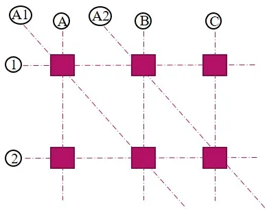
- A continuous center line that represents the structural axis.
- Each line got it named as alphabet or number.
- If you want to add sub axis then use a combination between both alphabet and number
Dimension lines
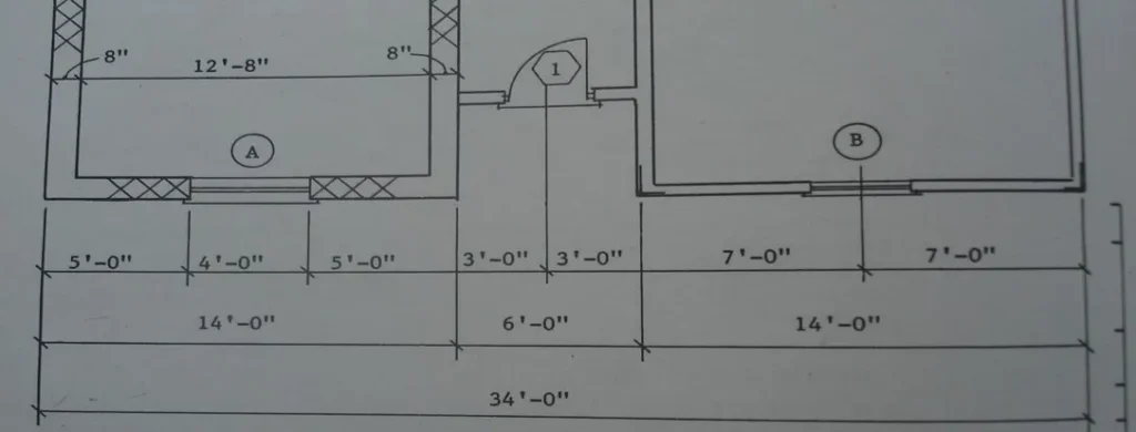
Mainly in outer dimensions there are three lines.
- First – for openings and any changes in wall, it is first after outer wall.
- Second – for the dimension between each 2 grid lines
- Third – the total dimension of building
Studio Work
Floor plan with evolved structural systems and Structural Grids. Dimensioning of Ground floor complete with levels, material finishes. Door/window designations.
Types of architectural plans in working drawing
- Floor plan with all internal and external dimensions is Dimension Plan
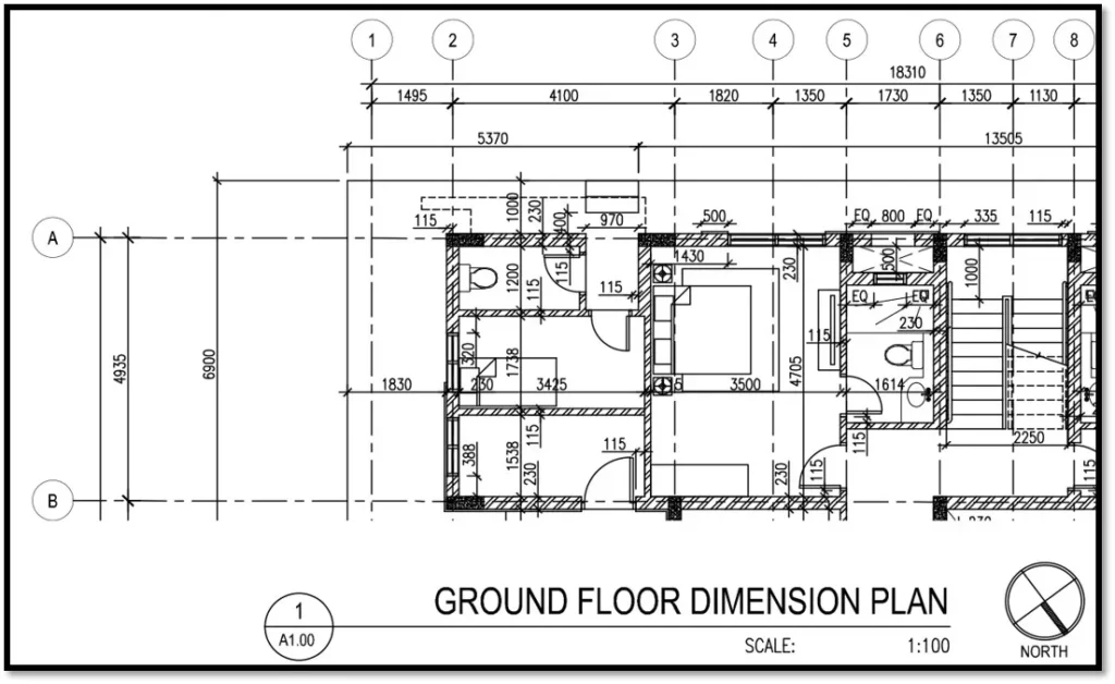
- Floor plan with all reference markings to the details is called Reference Plan

Checklist after making the floor plan
- Proper site and building are placed according to byelaws.
- Finalized the floor plans with proper.
- Wall thickness (outer and partition walls)
- Proper column layouts.
- Accurately placed doors windows and ventilators. With defined sill and lintel levels.
- All the objects are in specific layers with proper line-weights.
- Lifts are hatched.
- Staircase have shown proper UP, breaking line, Landing levels & dotted steps.
- Entrance steps and ramp are properly dimensioned.
- Dimensions are given for all brick work.
- Courtyard and other open to sky spaces are shown with dotted cross.
- Defined number of steps tread risers landing widths in staircases, and at building entrance.
- Ramp slopes and building entrances.
- Defined the sunken areas where toilets, Kitchen and other services based thing is present.
- Grid dimensions properly done.
- Text= 2.5 – 3mm (on sheet)
- Columns grey hatched.
- Walls hatched light.
- Title to every room corridor and open space is given.
- FCW marked and related with table for all finishes.
- D/W marked properly in drawing and seal.
- Key plan Marked, North marked.
- Upper floor projections are mentioned.
- Levels are marked in corridors on upper floors.
- Up and down are shown in upper floors.
- Windows have sun and rain protections.
- No furniture in plans.
- No text is overlapping the dimensions.
iii) Create external wall section
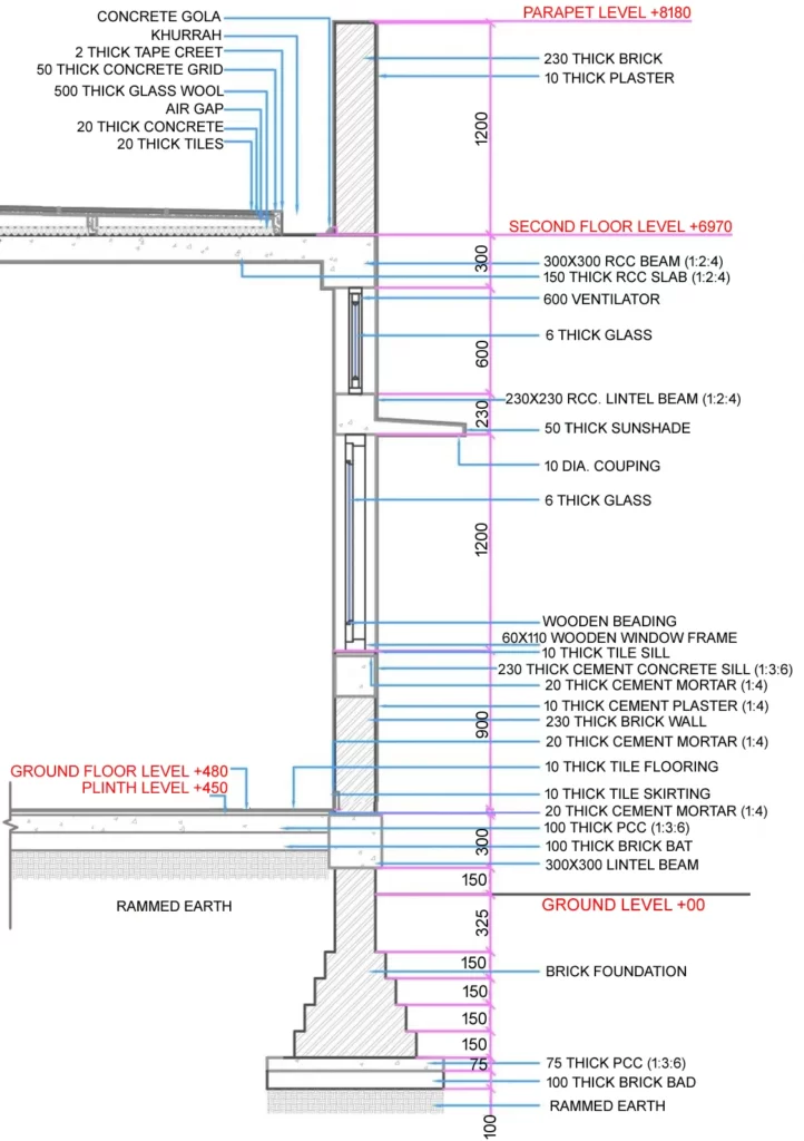
- Wall section illustrate exterior facade design detailing. They are extremely important illustration to ensure the final appearance of the design.
- Wall section should be shown from footing to roof peak without cutting the detail.
Wall Systems
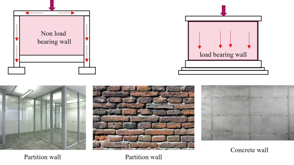
- Structurally:
- Load bearing and
- Non load bearing walls
- Functionally:
- Exterior and
- Interior (partition) Walls
- Based on Materials:
- Concrete
- Masonry
- Wood
- Steel
- etc.
Wall Section
Wall section describes in detail what the foundation, walls, floor systems and roofs are made of. So, we should be aware of:
- Foundation type and material
- Wall material
- Interior and exterior finishes
- Various heights
- Structural system
- Roof pitch
- Roof finish, etc.
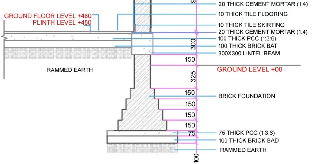
Foundation and floor
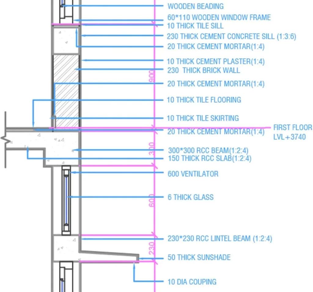
Wall and upper floor
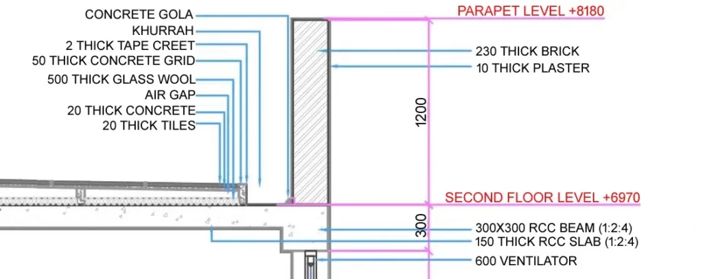
Terrace
Checklist after making the external wall section
- All dimensions and specification of components are given.
- Plinth level ground level and upper floor levels are defined.
- All necessary dimensions are provided.
- Different materials are represented with proper hatches.
- Details at foundation, sill, lintel and terrace are given at 1:5.
iv) Create foundation plan
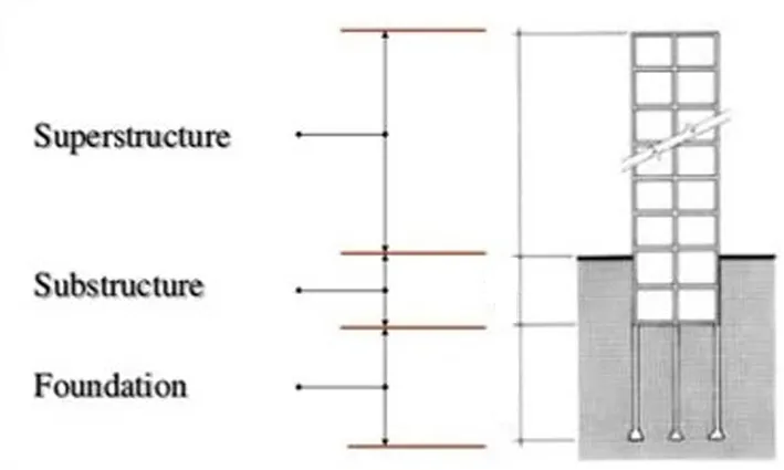
- The lowest part of the building constructed partly or wholly below the surface of the ground.
- Part of the substructure which is in direct contact with and transmit load to the ground
Primary function of foundation
- Support super structure.
- Anchor the building to the surface below.
- Transmit load to the ground.
Types of foundation
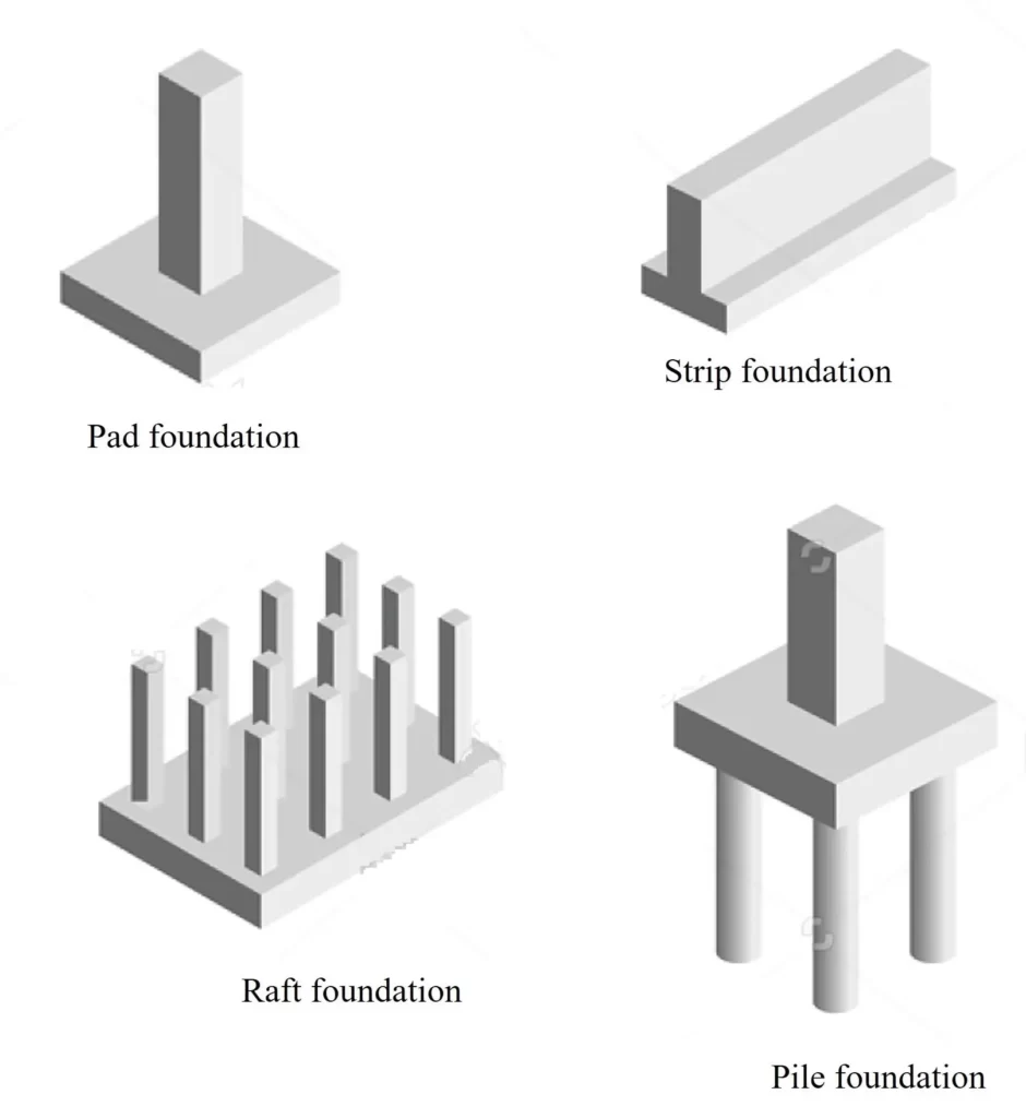
- Strip foundation
- Pad foundation
- Raft foundation and
- Pile foundation
Foundation plan
The foundation plan is a plan view drawing in section showing the location and size of footings, piers, columns, foundation walls, and supporting beam. Foundation plan is drawn at the same scale as the floor plan.
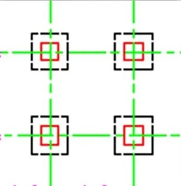
The foundation plan includes:
- Trench plan with dimensions
- Structural grid
- Footings for foundation walls and columns
- Foundation walls and columns
- Plinth Beams
- Details of foundation and footing construction
- Complete dimensions and notes
There are mainly five stages to draw a foundation plan:
- Trench layout
- Foundation layout
- Drawing the columns and beams
- Dimensioning
- Lettering
Checklist after making the foundation plan
- Grid dimensions properly done. (end centre to centre & overall)
- Text= 2.5 – 3 mm (on sheet)
- Columns grey hatched.
- Marked C1, C2 and PB1, PB2 (Plinth beams will be light and firm)
- Trench shown with dimensions.
- Two typical sectional details are given (footing and foundation).
- Marking of footing properly done in drawing as well as in table.
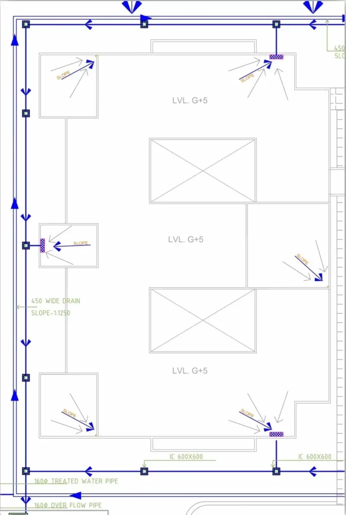
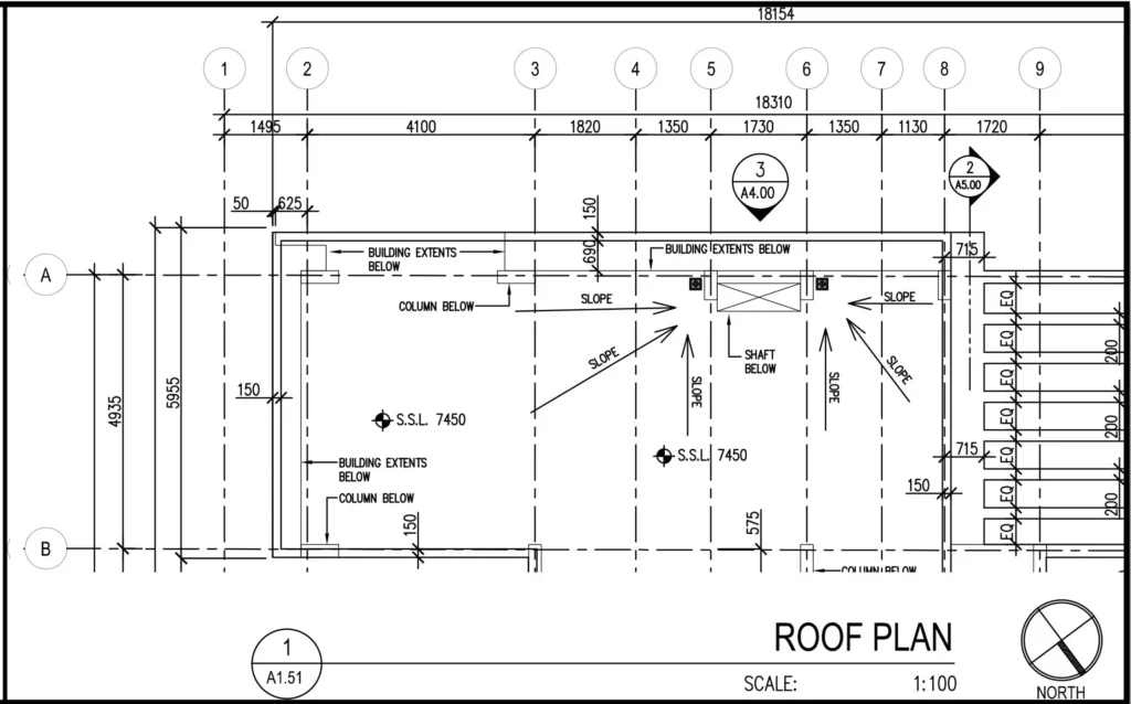
v) Create terrace/roof plan
Top view of building. Explains the overall configuration of the roof and the elements that penetrate or rest on the roofing membrane. It is usually drawn at the same scale as the floor plan.
Roof plan shows
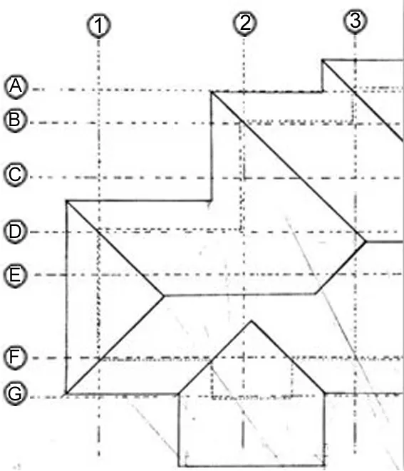
- Over hangs, Canopies and Roof surfaces
- All dimensions to walls, column center lines or other permanent features
- Mark levels at various points wherever required.
- Roof stricture, Roof finishes
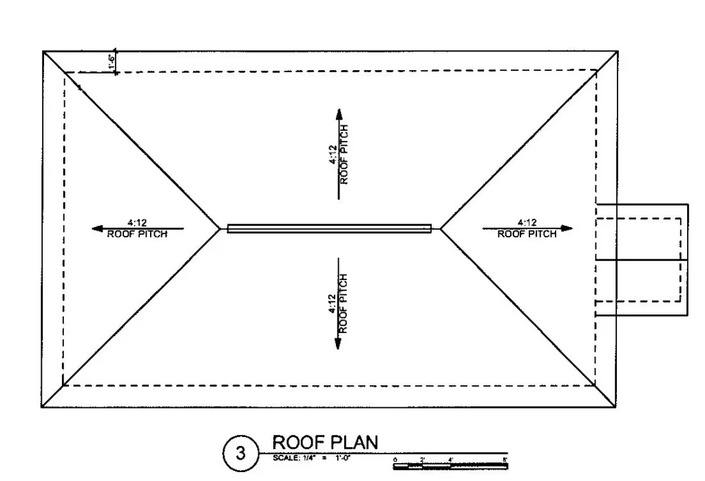
Drainage of roof:
- Direction of water movement (Slope)
- Drains
Description and dimensions of:
- Gutters (Khurrah) and down pipes
- Parapet walls
- Other structures if left for future expansion.
- Building line (edge) in hidden while roof overhang in solid line
Checklist after making the terrace plan
- Mumty is shown with all down steps.
- Terrace level and last landing levels are mentioned.
- Khurrah is marked with size and number of RWP with pipe dia.
- Parapet marked.
- Ridge lines are mentioned.
- Slope mentioned.
- Detailed terrace section is detailed out.
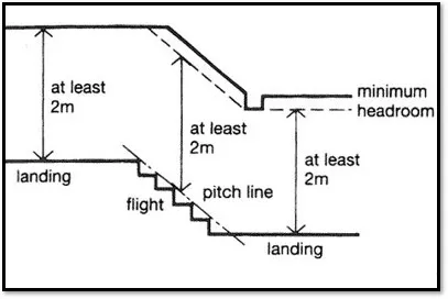
vi) Create staircase
A Stair is a system of steps by which people pass from one level of building to another. So, a stair is designed to cover a large vertical distance by dividing it into smaller vertical distances, called steps.

Components of staircase
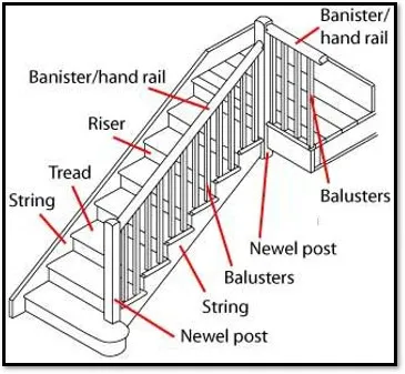
Tread and Riser
- In a flight all steps have same riser and same tread.
- Tread riser relationship should be as 2R+T = 63cm
- Handrail 90-100 cm
Types of staircases
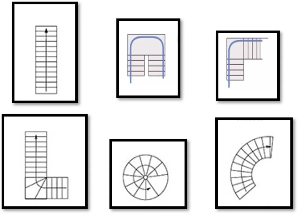
- Straight
- Dog leg
- L Shape
- Winder
- Spiral
- Curved
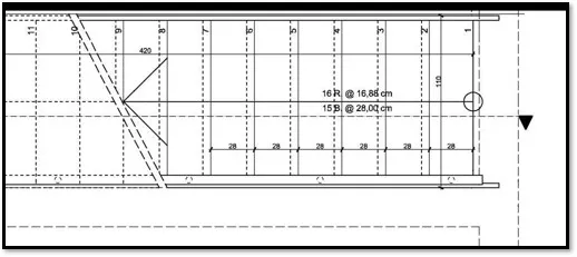
Staircase detail
- Number each step Starting from lowest.
- Indicate all dimensions.
- Indicate all specifications and elements like handrail on plan and section.
- Draw all floor plans and in a single-story draw both up and down plan.
- Section showing all details and levels.
- Joining details like handrail, etc.

vii) Create elevation and section
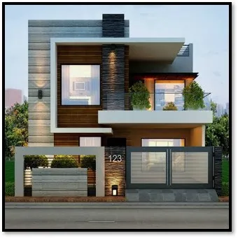
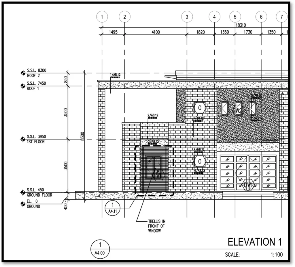
Elevation
Elevations provide viewers a better understanding of the scope and complexity of a project than any other drawing type. Elevation should illustrate exterior finishing materials, levels, dimensions, centerlines, and details.
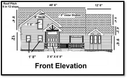
Elevation detail
- Show the exterior and interior elevations of the building.
- Indicate the heights of windows, doors, and rooflines.
- Show the location and type of materials used for cladding, roofing, and flooring.
- Grid lines.
- Levels.
Section detail
- Section drawings provide a cutaway view of a building from the side to reveal what lays beneath the surface of each building element the section cuts through.
- In a drawing there are generally two building sections that show a complete section view of entire length and width of the building respectively.
- The main purpose is to illustrate the information that cannot be easily derived from other drawings.

- Section should illustrate vertical information including levels, materials, dimensions, corresponding centerlines and details cross-referencing.
- Show interior features.
- Complete vertical dimensions.
- Specifications.
- Grid lines.
Checklist after making the elevation and section
Elevation Checklist
- North South-East West elevations are mentioned.
- Key plan must be related with elevations.
- All surface ad sectional levels are marked.
- No unnecessary lines will be there until there is any level change.
Section Checklist
- 2 sections are required from toilet and staircase.
- All the detailing of external wall will come on external wall.
- Plinth beams will be there below the walls.
- Grids are marked.
- Key plan must be there on seal (not the site plan but the G.F plan)
- All levels marked.
viii) Create site plan
- The site plan should show the location of the building in relation to the site boundaries.
- All landscape elements, streets and pedestrian should be indicated and dimensioned.
- Surrounding buildings, Streets should be marked.
- Drain lines should be marked.
- Trees should be marked both existing and proposed.
- So, it shows landscaping, driveways, ground levels, mains water, and other information relevant to the work being carried out, with legends.
Checklist after making the site plan
- Site dimensions and surrounding is marked.
- North marked.
- Roads are mentioned with widths.
- Building outer profile id dark and hatched with levels name and area written.
- Mumty Hatched.
- Plumbing marked with slope directions and invert levels.
- All the different zoning of site is given.
- Levels are marked on important places like green areas, parking, pedestrian pathways and buildings.
- Guard room is shown in single line.
- Properly composed.
- Are chart and statements are provided.
ix) Toilet details
- One section through the toilet for discussions. The scale of the above drawings shall be 1:25.
- 1 plan and four sections are given.
- Grid, wall hatch columns and shafts are there.
- Tiles line very light are given on floors as well as wall sections.
- Drop with symbol is mentioned.
- Floor trap, fixtures, valves, mirrors, are marked.
- Center to center and overall dimensions of fixture is given.
- WC internal dimensions will be referred from the reference drawings.
x) Kitchen Details
- One Plan & section through the Kitchen for discussions. The scale of the above drawings shall be 1:25.
- 1 plan and four sections are given.
- Grid, wall hatch columns and shafts are there.
- Tiles line very light are given on floors as well as wall sections.
- Drop with symbol is mentioned.
- Floor trap, fixtures, cabinets are marked.
In conclusion, a good construction drawing is essential for a successful construction project. It provides a clear visual representation of the project and helps everyone involved in the construction process to understand the project requirements and make informed decisions.