
If you want to know about the water supply requirements for building or rainwater disposal system or piping system for soil and waste drainage, please click the link.
A sanitation system is a set of practices, facilities, and infrastructure designed to promote public health by safely managing human waste and other potentially harmful substances. A properly functioning sanitation system is critical for preventing the spread of disease, protecting the environment, and maintaining the health and well-being of communities.
1) Important Terms
i) Waste
Anything which is eliminated or discarded as no longer useful or required after the completion of a process. The waste may be in any of the following states:
- Dry
- Semi liquid
- Liquid.
Dry waste
The waste which does not contain moisture is called dry waste. It is comprised of the following items:
- Rubbish: all sun-dry solid wastes as paper, leaves, grass, broken furniture waste building material.
- Ashes: residues remained after the combustion of coal, timber in the hearth and furnaces.
- Garbage: semi solid and solid waste food products as vegetables, peelings of fruit, waste meat.
Semi liquid
- Waste which contains organic matter. i.e. human excreta or night soil.
Liquid waste
- It consists of water and very less organic matter. It is a discharge from kitchens, wash-basins.
- Branch Special form of sewer pipe used for making connections to a sewer or water main. The various types are called ‘T’, ‘Y’, ‘T–Y’, double Y and V branches, according to their respective shapes. Any part of a piping system other than a main or stack.
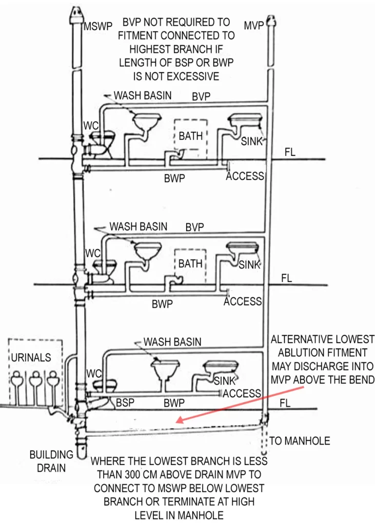
- Branch Soil Pipe (BSP) – A pipe connecting one or more soil appliances to the main soil pipe.
- Branch Waste Pipe (BWP) – A pipe connecting one or more waste appliances to the main waste pipe.
- Branch Soil Waste Pipe (BSWP) – A pipe connecting one or more soil and/or waste appliances to the main soil waste pipe (one pipe system).
- Branch Ventilating Pipe (BVP) – A pipe, one end of which is connected to the system adjacent to the trap of an appliance and the other to a main ventilating pipe or a drain-ventilating pipe. It is fitted to prevent loss of water seal from a trap owing to partial vacuum, back-pressure caused by air movement within the pipe system. It also provides ventilation for the branch waste pipe.
ii) Building drainage
- The arrangement provided in a building for collecting and conveying the waste through drainpipes by gravity to join a sewer is known as building drainage.
For the design of drainage and sanitation system the aim shall be:
- to dispose off liquid waste as early as possible
- to safeguard against foul air entering the building,
- to safeguard against deposition of solids and clogging and
- adequate cleanouts and inspection chambers so arranged that the drains may be readily cleaned without the risk of health hazard.
Requirements of building drainage:
- Layout of the building drainage must be simple.
- Layout of the building drainage must allow quick removal of foul waste matter.
- Drains should have self cleaning velocity.
- Diameters of the drains must be sufficient for carrying domestic sewage and sullage.
- Branch drains should be as short as possible
- Drainage system must be ventilated properly.
- The plumbing system shall be designed and adjusted to use the minimum quantity of water consistent with proper performance and cleaning.
- Plumbing fixtures, devices and appurtenances shall be supplied with required volume of water at pressures adequate to enable these to function properly and without undue noise under normal conditions of use.
- The drainage system commences within the premises at the plumbing fixtures, where the water that is supplied to them is used or washed and is then drained into the drainage pipes and finally into the public sewer or to an individual waste disposal system.
- Thus, in any building, there is both the beginning of the sewerage or drainage system and the termination of the water supply system.
- SLOPE- minimum slope of a drainage pipe should be 2% or 20mm/m (¼” per ft).
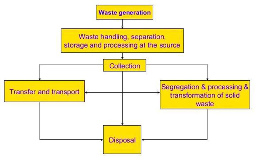
2) Functional elements of soil waste management system
3) Sanitary fittings
- It indicates all the fittings or appliances used for collecting and discharge of soil or waste water.
- Material- Ceramics, glazed fire-clay, glazed earthenware.
- The fittings are designed so as to have non – absorbent surface which can be easily cleaned.
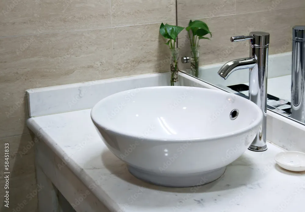
- Wash-basins
- Bath tubs
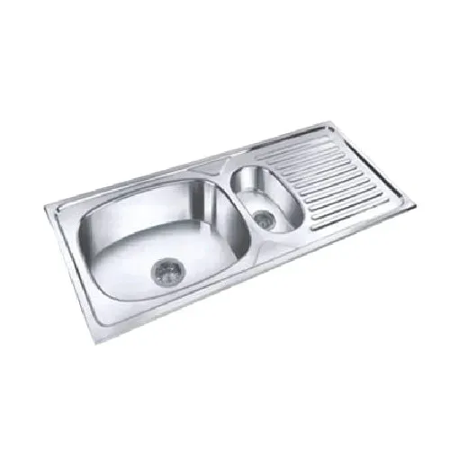
- Sinks
- Urinals
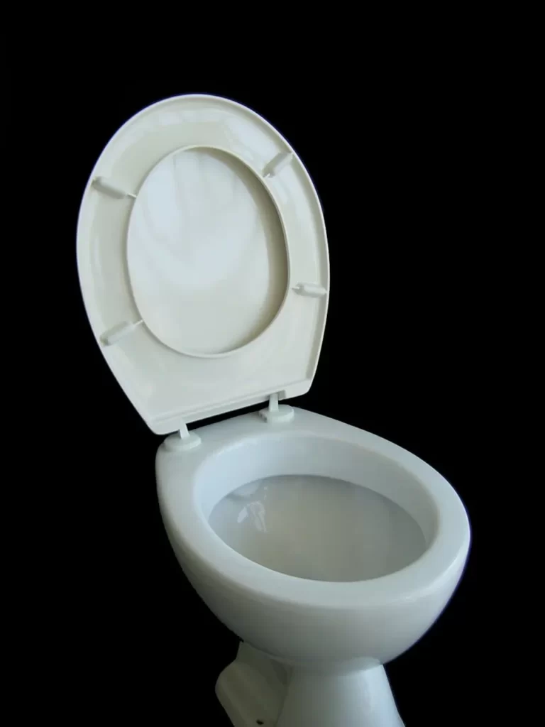
- Water closets
- Flushing cisterns
i) Wash basin
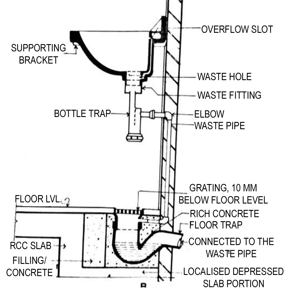
- It is connected directly or through bottle trap for discharge of waste water into the floor trap.
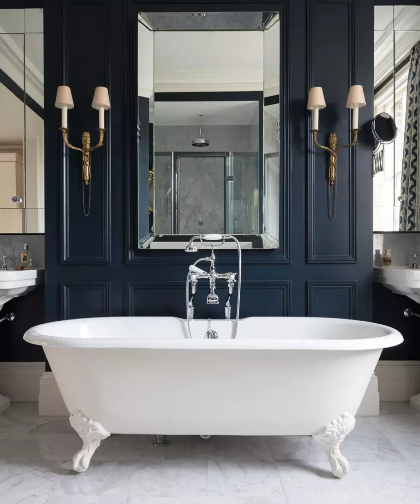
ii) Bathtub
iii) Wash basin
iv) Sink
v) Water closet
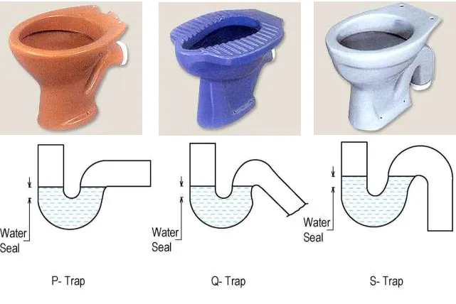
4) Traps
- A trap is a fitting provided in a drainage system to prevent entry of foul air or gases from the sewer or drain into the building.
- The barrier to the passage of foul air is provided by the water seal in the trap.
- A trap is merely a double bend or loop in the sanitary fitting.
- The depth of the water seal varies from 40mmto 75mm.
i) Types of traps (depending upon the shape)
ii) Essentials of a good trap
- an efficient ‘water seal’,
- to be self-cleansing,
- Should not retard the flow of water unduly,
- should retain a minimum amount of water consistent with its purpose.
- Every trap should be provided with means of access.
- The inner surface of the access cap should conform to the internal line and curve of the fitting.
- Traps are useless unless they retain their seals at all times. The seals may be broken ,in the following ways:
- a) siphonage,
- b) air compression,
- c) Momentum
- d) Evaporation
- The remedy for (a) and (b) is adequate means of trap ventilation. In the case of (c), an anti-D trap which retards the flow, should be used. In the case of (d), evaporation may occur in fittings left unused for lengthy periods.
- A film of glycerine poured into the trap is an effective remedy. The traps of fittings fixed in range are liable to siphonic action and each trap should be ventilated.
iii) Types of traps (depending upon the location and use)
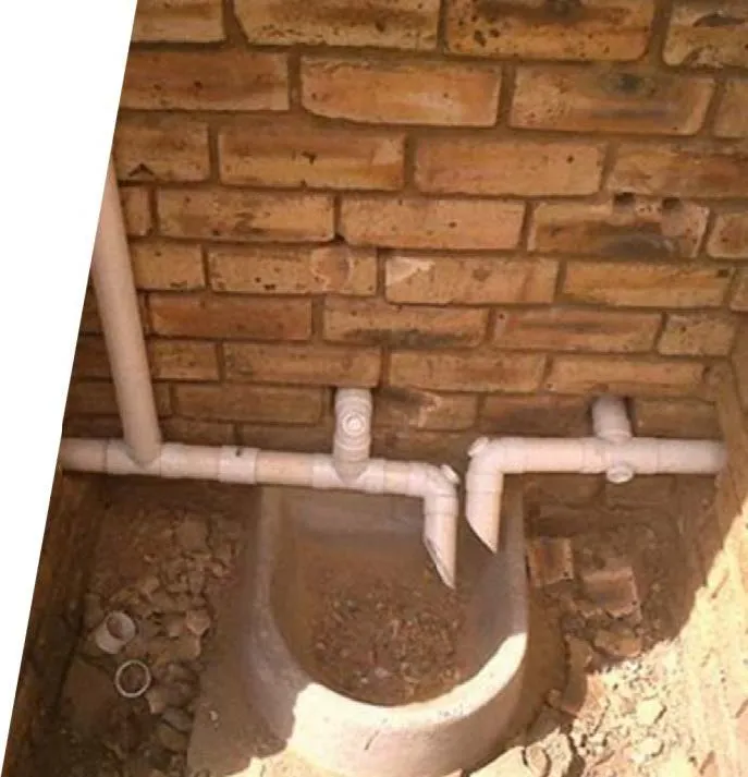
- Floor trap (nahani trap)
- Gulley trap
- Intercepting trap
- Grease and oil traps
Floor trap (nahani trap)

- Provided in floors to collect waste water from kitchen sinks, bathroom floors, washing floors etc.
- It forms starting point of waste flow.
- Material – Cast Iron or PVC
- Depth of water seal should not be less than 40mm.
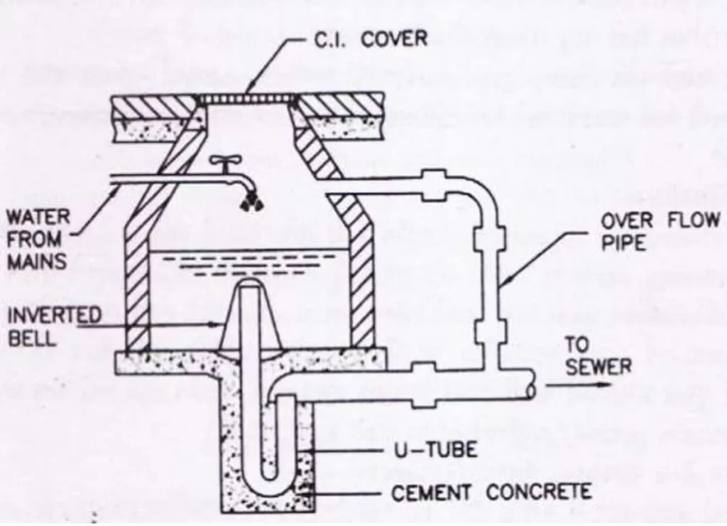
Gulley trap
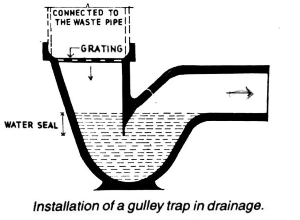
- Location- It is usually situated near the external face of the wall.
- Function- It disconnects the waste water flowing from the kitchen, bathroom, wash-basin and floors from the main drainage system.
- This is a deep seal trap forming a barrier for preventing the foul gases from house drain to the inside of the building.
- Material – Cast Iron or Glazed stoneware.
- Grating is provided on the top to retain all solid matter.
- The water seal of about 60-70mm .
- Provided in waste pipe only.
- Maximum distance between gulley trap and the first manhole should be 6000 mm.
Intercepting trap

- Location- It is provided at the last manhole i.e. at the junction of house drain (inspection chamber) and the public sewer so as to prevent the entry of foul air from public sewer.
- Material – Glazed stoneware
- It is provided with an inspection arm for the purpose of cleaning.
- Water seal not less than 100mm deep.
Grease and oil traps
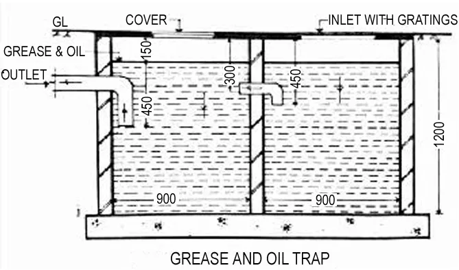
- Function- These chambers are provided on the sewer line to exclude grease and oil from sewage before it enters the sewer line.
- Location- near the sources contributing grease and oil to sewage.
- If grease or oil is not removed, it sticks to the sides of sewer, reducing its capacity.
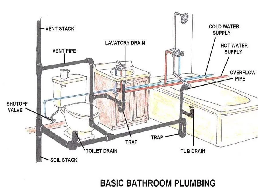
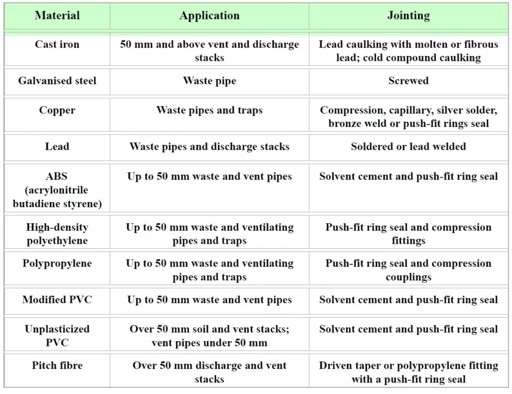
5) Pipes
- Soil pipe (100 mm): A soil pipe is a pipe Through which human excreta flows.
- Waste Pipe (horizontal 30-50mm, vertical 75mm): It is a pipe which carries only the liquid waste. It does not carry human excreta.
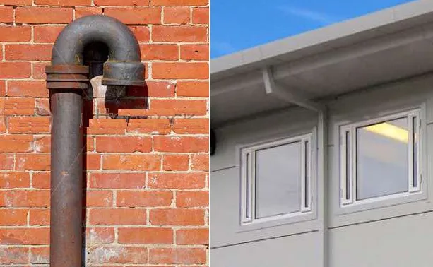
- Vent pipe (50mm): It is a pipe which is provided for the purpose of the ventilation of the system. A vent is open at top and bottom, to facilitate exit of foul gases. It is carried at least one meter higher than the roof level.
- Rain water pipe (75mm): It is a pipe which carries only the rain water.
- Anti-siphonage pipe: It is pipe which is installed in the house drainage to preserve the water seal of traps.
6) Sanitary System
i) Pipes
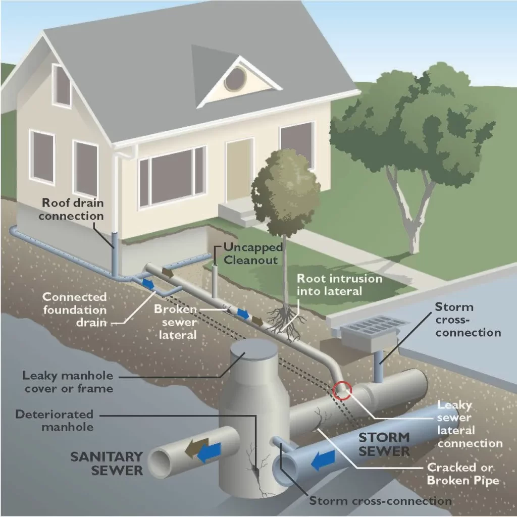
7) House drainage
- It includes the collection of soil and waste from sanitary fixtures and their conveyance to public sewers through traps and intercepting chamber.
- It includes two methods:
- Conservancy system
- Water carriage system
i) Conservancy system
- Different types of refuse are collected separately. Each type is then carried for treatment and disposal
- Very cheap in initial cost.
- For burial of excremental matter large area is required.
- Fully dependent on human agency so in case of strike by the sweepers, there is a danger of insanitation conditions.
ii) Water carriage system
- Water is the main medium to convey the sewage to the final point of treatment.
- It involves high initial cost.
- Less area is required as compared to conservancy system.
- As no human agency is involved in this system there is no such problem as in the case of conservancy system.
- Sewage is carried in properly laid sewers.
8) System of sewerage
Any of the following four systems can be used for the conveyance of refuse from the sanitary fitting to the house drain, depending upon the number of pipes used:
- One- pipe system
- Two – pipe system
- Partially ventilated single stack system
- Single stack system
i) One- pipe system
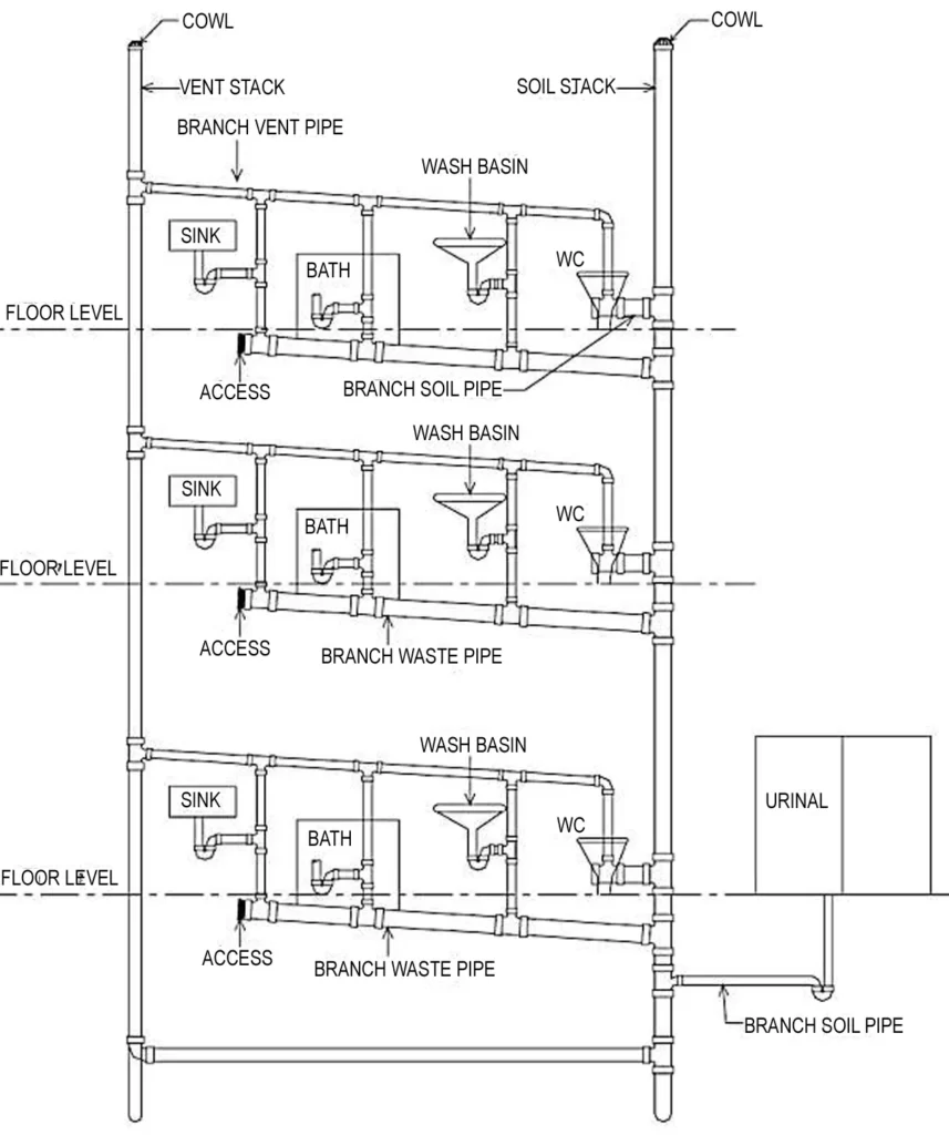
- Only one set of pipes is used – main soil waste pipe and main vent pipe.
- All the contents of kitchen sinks, bathroom floors, wash-basins and water closets are discharged into a single pipe.
- The soil waste pipe is directly connected to the building drain.
- Common Vent pipe – min 50mm dia for both soil and waste appliances.
- All traps should have water seal of min 75mm deep.
- More economical than two pipe system.
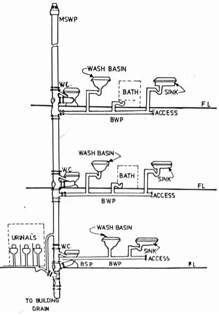
ii) Two – pipe system
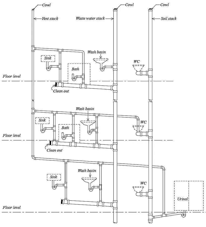
- Two sets of pipes are used for drainage – soil pipe with vent pipe and waste pipe with vent pipe.
- All contents of WC and urinals are discharged into soil pipe.
- The waste pipe contains waste water from wash basins, sinks, bathroom floors etc.
- The soil pipe is directly connected to the building drains
- The waste pipe is connected to the building drain through the gulley trap.
iii) Partially ventilated single stack system
- Single soil cum waste pipe carries the discharge from WC, urinals, bathrooms, sinks etc.
- The traps of soil fittings, i.e., WC and urinals only are ventilated through single vent pipe.
iv) Single stack system
- This system single vertical pipes which acts as main soil cum waste pipe and in addition to it acts as vent pipe.
- This is very economical system, but all the traps should have a water seal of not less than 75mm to prevent breaking of water seal due to siphonic action.
9) Sewer appurtenances
These are necessary devices for the proper functioning of any complete sanitary system. These includes the following:
- Manholes
- Flushing tanks
- Clean outs
- Catch basins
- Lamphole
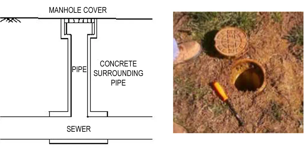
i) Manholes
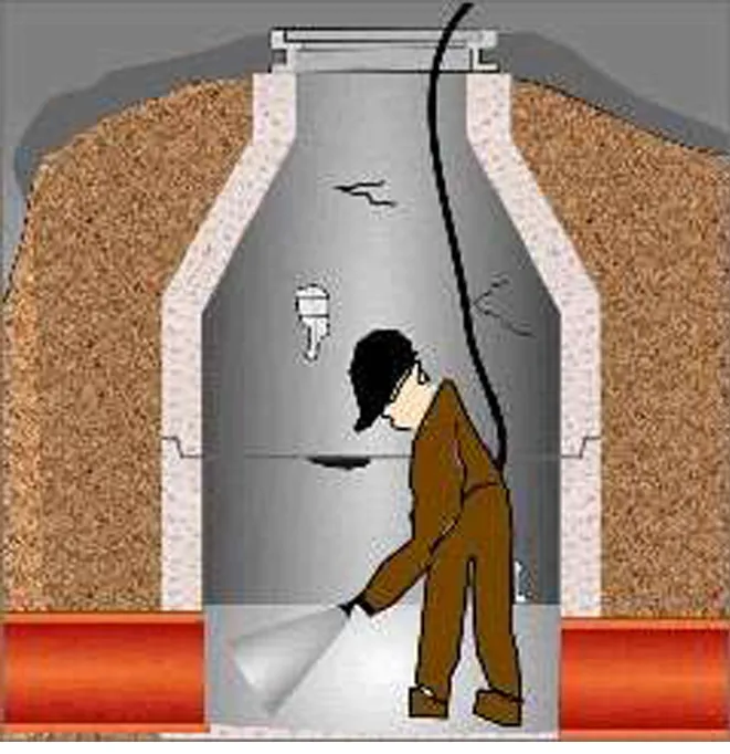
- These are provided along the drains at short distance to facilitate the entry of a person for the cleaning or maintenance of sewers.
- Maximum distance between two manholes should not be more than 30m.
- Maximum dimensions should be 1200 x 900 mm, opening 500mm.
ii) Catch basins
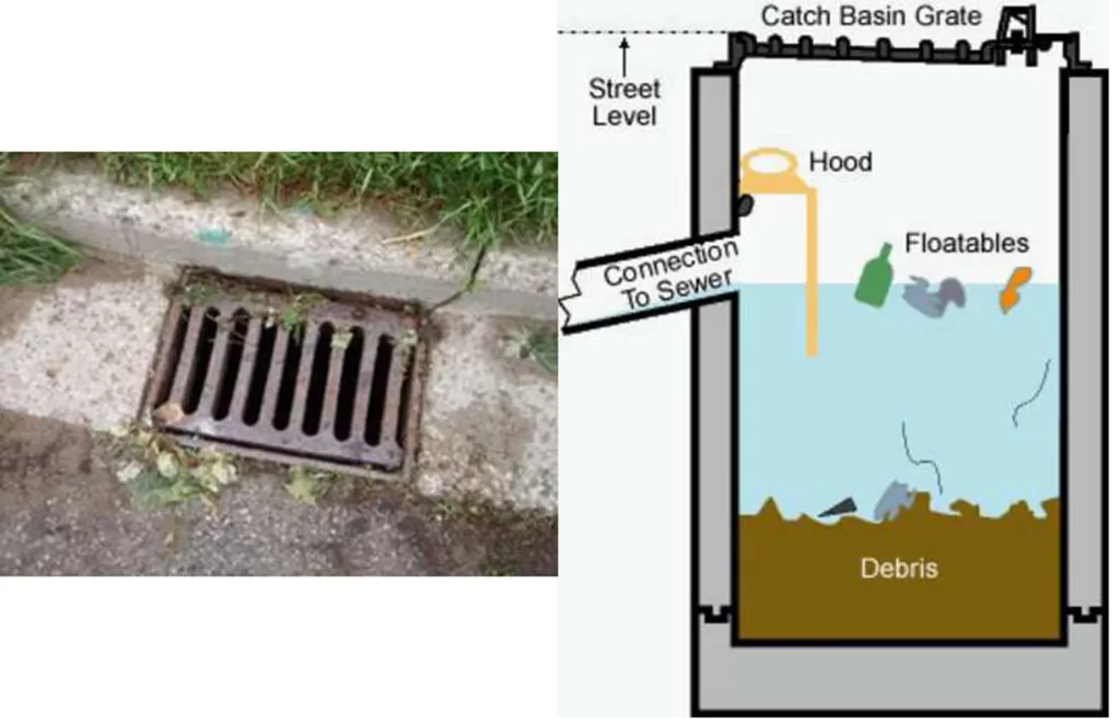
- These are used in combined sewer system.
- It is a structure in the form of a chamber provided along the sewer line.
- It is provided for the retention of heavy debris in storm water.
iii) Clean outs

- It is used to clean the underground sewers.
iv) Flushing tanks
- It is arrangement which holds and throws water into the sewer for the purpose of flushing it.
v) Lamphole
- It is an opening in the sewer from which a lamp can be lowered inside.
Purpose-
a. Inspection of sewers between adjacent manholes.
b. May be used as flushing devices.
c. Ventilation of sewers by providing perforations in the cover at the top.
10) Conveyance of refuse
It includes the following methods:
- Separate system
- Combined System
- Partially Separate system
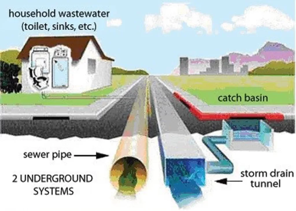
i) Separate system
- In separate system of sewerage two sets of sewers are laid .One for carrying storm water and other for carrying sewage.
- System is cheaper because sewage is carried in underground sewers and storm.
- The quantity of sewage to be treated is less, because no treatment of storm water is done.
- In the cities of more rainfall this system is more suitable.
- In narrow streets, its difficult to use this system.
- Less degree of sanitation is achieved as storm water is deposed without any treatment.
ii) Combined System
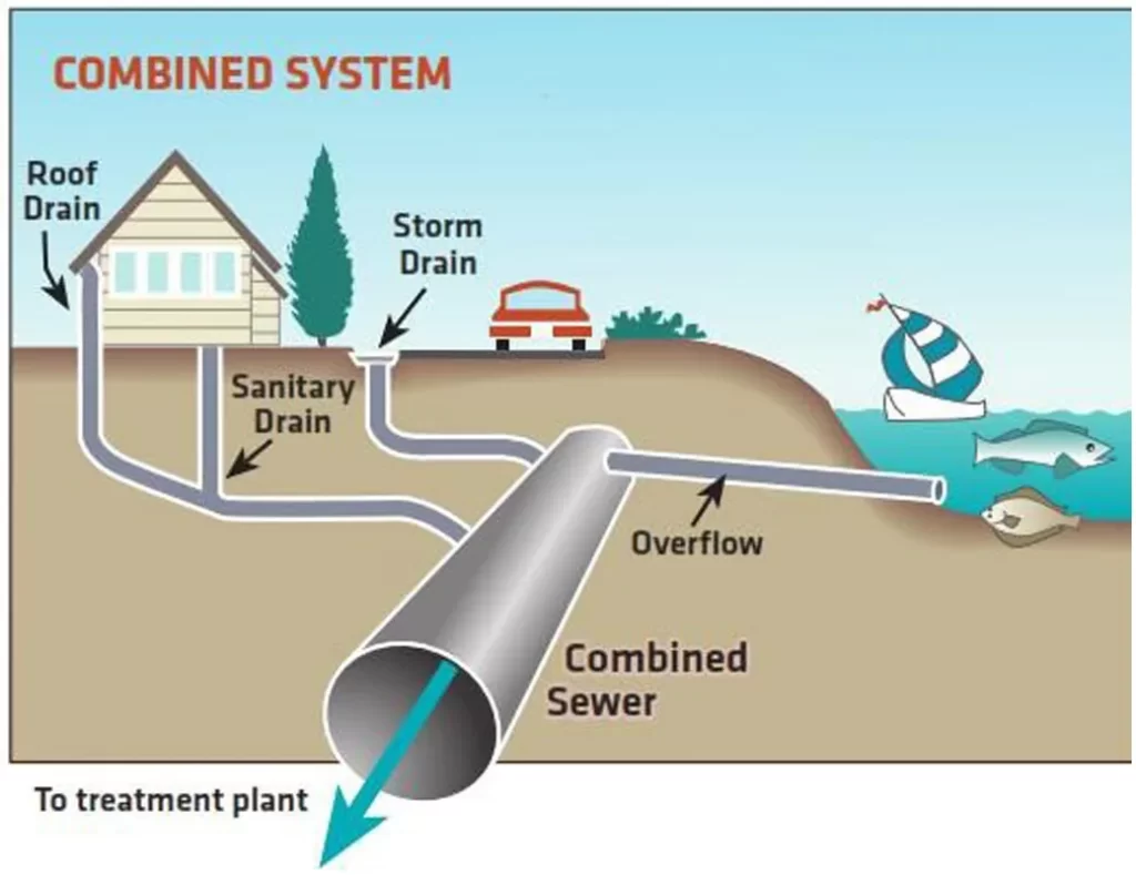
- Only one sewer is laid which carries the sewage as well as storm water.
- Overall, construction cost is higher than separate system.
- As the treatment of both are done, the treatment is costly.
- In the cities of less rainfall this system is suitable.
- It is more suitable in narrow streets.
- High degree of sanitation is achieved in this system.
iii) Partially Separate system
- The storm water is allowed to flow into the sewers containing sewage upto a partial limit only.
- Once the quantity of storm water exceeds that limit, the same is allowed to flow in open drains where they are directly discharged into rivers or streams.
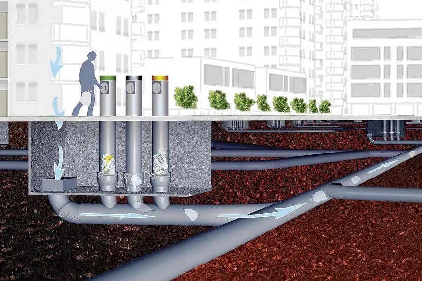
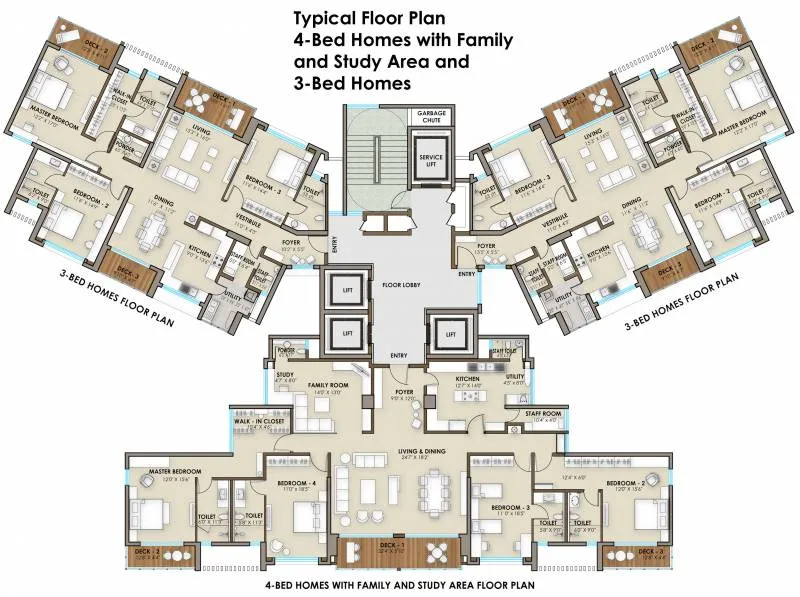
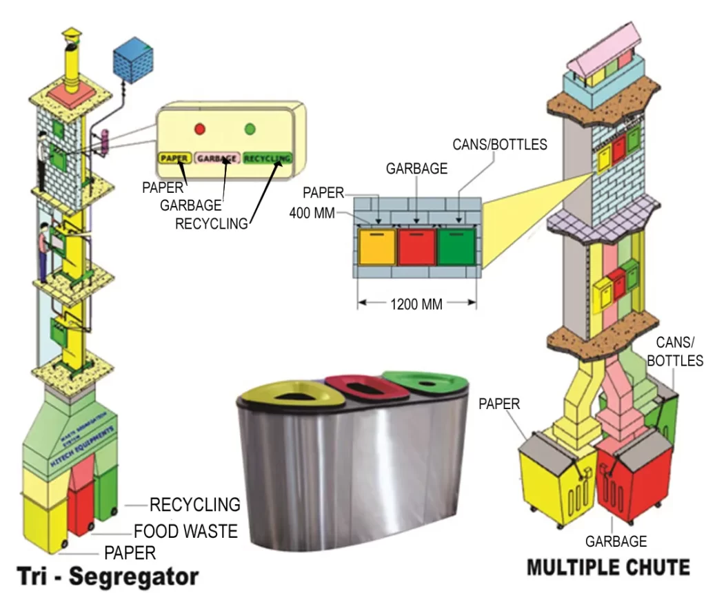
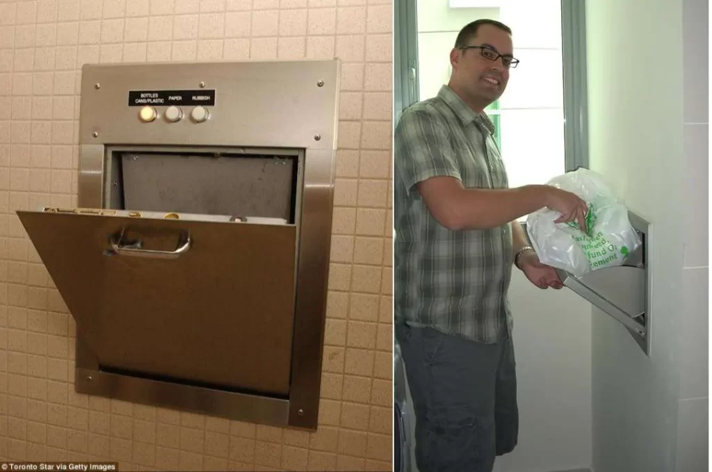
11) Refuse chute system
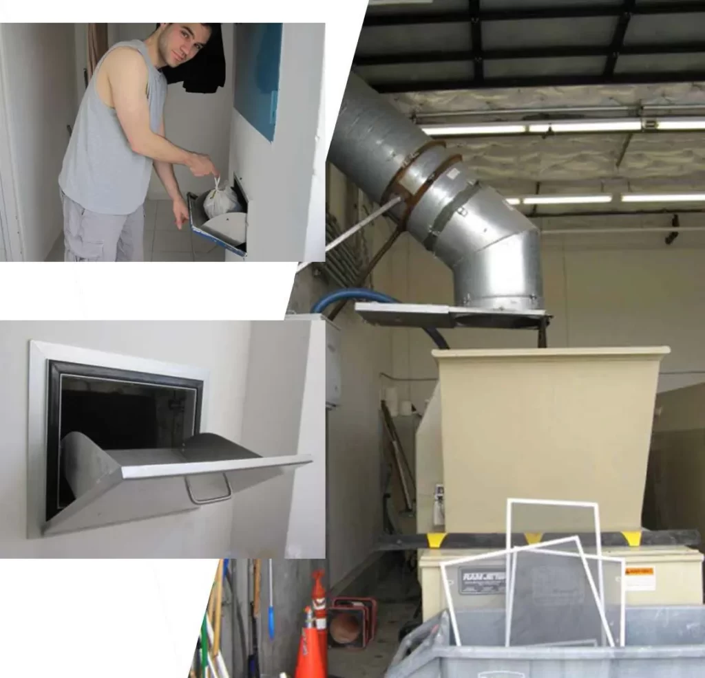
- A refuse chute is an inclined channel in which refuse can be passed down from the opening of each floor to the central refuse room on the ground floor of a building.
- Chutes may be round, square or rectangular at the top and/or the bottom.
- Garbage chutes can be installed in Residential, commercial buildings and malls. In any duct, common lobbies, landings, staircase mid-landings, utility ducts, dry balconies and kitchens.
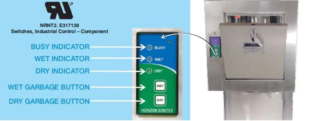
Advantages of Garbage Chutes
- Facilitates total building garbage collection at one single point.
- Garbage disposal with ease & utmost hygiene.
- Reduces Power consumption.
- “Dry” & “Wet” garbage separate collection possible.
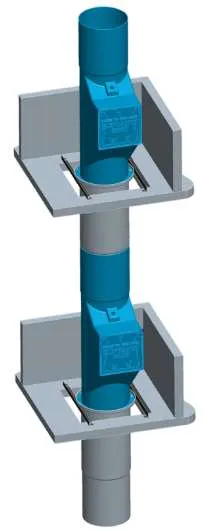
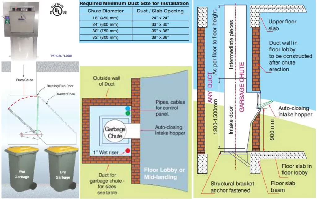
- Reduces manpower. Refuse chute system is a convenient and safe mode of collection of domestic solid wastes from buildings exceeding 3 storeys. Internal diameter of the chute shall be at least 300mm.
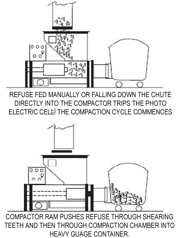
- The refuse is received from the successive floor through the inlets located on the vertical system of pipes that convey refuse through it and discharge it into the collecting chamber from where the refuse is cleared at suitable intervals.
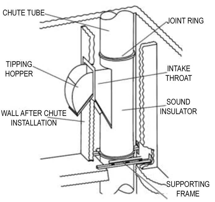
- This system has got three functionally important components,
- the chutes,
- the inlet hopper and
- the collection chamber.
- The chute may be carried through service shafts meant for carrying drainage pipes.
- However, the location shall be mostly determined by the position of the inlet hopper and the collecting chamber that is most convenient for the user.
- It should also be considered to locate the chute away from living rooms in order to avoid noise and smell nuisance.
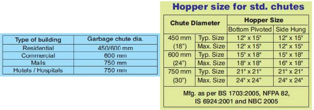
15) Selection of Chute Diameter
- Garbage generation varies, thus garbage bag size varies. As per garbage bag size, intake hopper size is selected.
- As per hopper size diameter of chute is selected.
- Laundry/Linen chute typical diameter 750mm.
A well-designed and maintained sanitation system can have numerous benefits, including reduced incidence of waterborne diseases, improved public health, and enhanced environmental sustainability. However, achieving these benefits requires ongoing investment in infrastructure, public education, and policy development.