
If you want to know about the element of design or about the lift and their components or air distribution system, please click the link.
Traffic analysis is an important part of designing an effective elevator system. The goal is to optimize the flow of people in and out of the building, minimizing wait times and maximizing efficiency. To do this, designers must consider several factors, such as the building’s population, the distribution of floors, the types of activities taking place in the building, and the time of day.
One of the key decisions that designers must make is the selection of lifts. There are several types of lifts, including geared and gearless, hydraulic, and machine room-less (MRL) lifts. Each type has its own strengths and weaknesses, and the decision should be based on the building’s specific needs.
Traffic analysis
- A lift traffic analysis studies the performance of a group of lifts, based on assumptions about the expected traffic situation. … Handling Capacity is expressed as the percentage of the building population the group of lifts can cope with over a given time period (usually in 5 minutes).
1) Handling capacity
- Handling capacity (Quantity of service) or the passenger carrying capacity of the lift. This can be defined as percentage of the population of building, which can be carried one way in the period of 5 minutes.
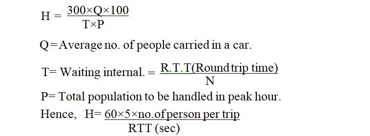
Table – 1

2) R.T.T. (Round trip time)
The round-trip time is equal to average time required by lift in taking the full load of passengers from ground floor, discharging them in various floors and coming back empty to ground floor taking the fresh passengers in the next trip including time taken for-
- entry and exit of passengers.
- Door closing and opening time on all floors.
- Acceleration, stopping and levelling period.
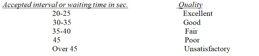
3) Waiting Interval
- Waiting Interval or quality of service is generally measured in terms of average passenger waiting time at various floors.
- Recommended quality of service is given below.
Table – 2
4) Rated load
- Rhe rated load is the maximum load for which the lift car is designed and installed to carry safely at its rated speed.
- Rated speed – is also known as the car speed. It is the speed for the lift designer to move efficiently with a given rated load.
5) Rated Speed
- Rated Speed is also known as the car speed. It is the speed for the lift designed to move efficiently with a given rated load. Lift speed up to 2.5m/s is recommended. Slower speed may be used for heavier loads.
Table – 3
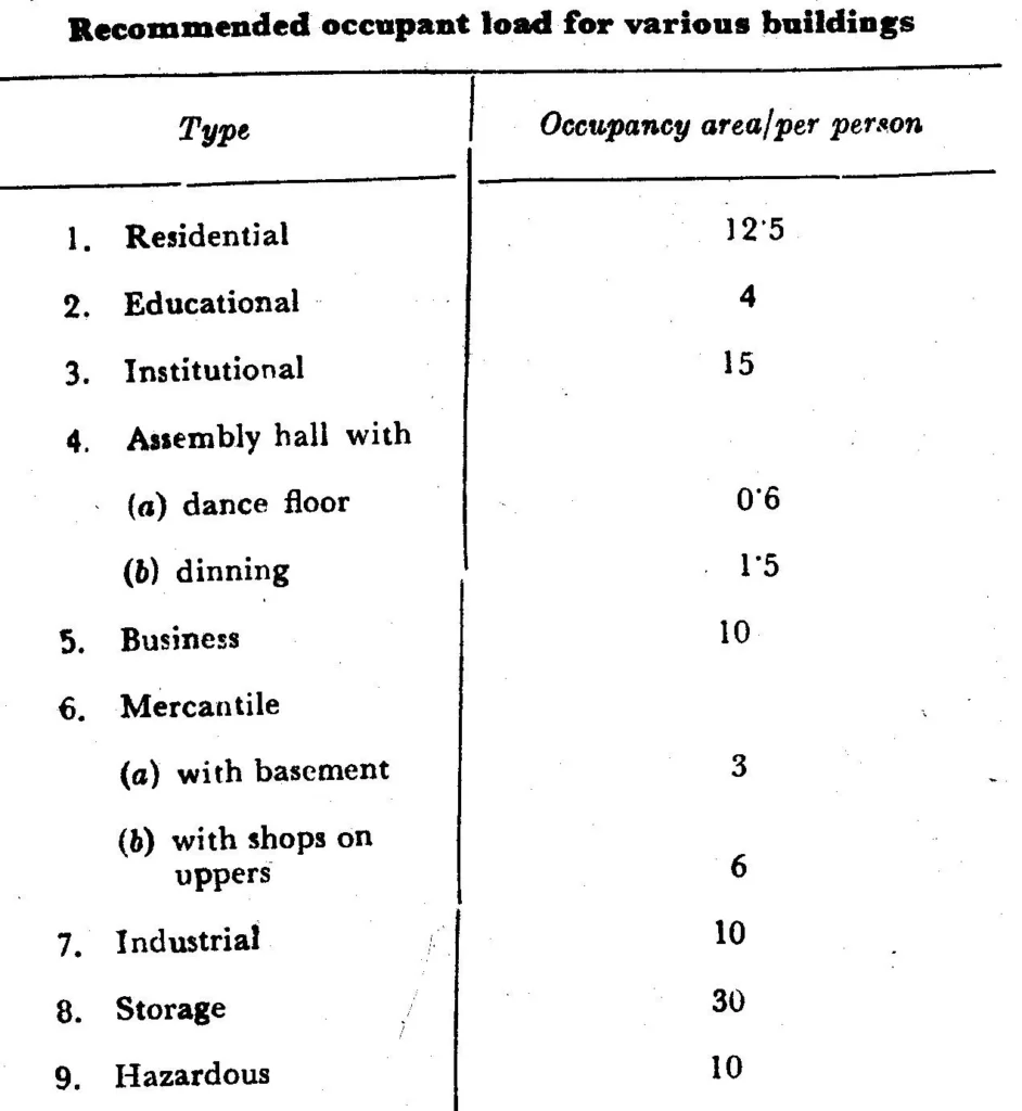
- For more information click here – Occupant load calculation
- For selection of lift first population is calculated based on occupancy type of building. Floor occupancy on average is being taken as 9.2 sq m of net carpet area per person but for minute calculation refer table given left-
Table – 4

Table – 5

Table – 6
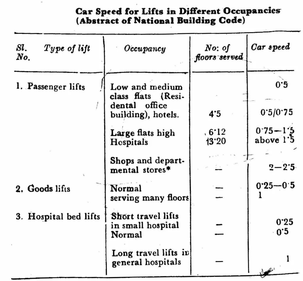
Table – 7

Table – 8

6) Example
Question) – Determine the number of lifts required in a rectangular Institutional government building, single occupancy having ground with 14 upper floors with uniform floor to floor height of 3.28m and main lobby at ground floor. Gross floor area is 2000 sq m at all floors.
Solution) – From table-3 occupancy area per person of institutional building is 15 sq m.


6) Design criteria and planning of lifts
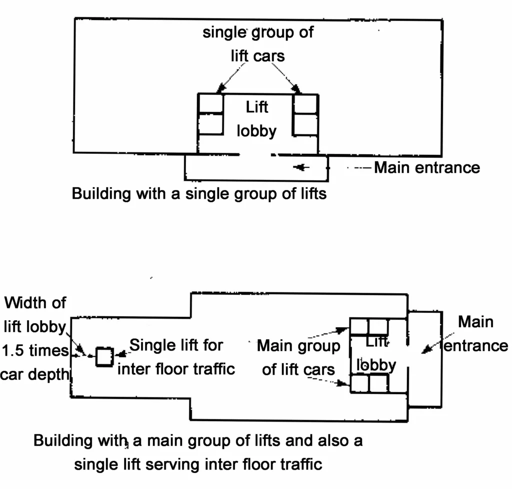
- In large buildings area tends to be 5-6m2 per elevator on upper floors and 15-20m2 per elevator on ground floor with single group of elevator.

- For tall building in excess of 15 storeys, high speed express lifts may be used which by-pass the lower floors.
8) Works to be done in lift installation by Owner
- Lift shaft, waterproof pit and machine room duly ventilated and provided with electric supply 3 phase 50 hertz 415 volts AC.
- Trap door and hoist hook in machine room.
- Cut outs on machine room for governors and driving rope and trap door during construction period.
- Cad ladder in pit and lighting in hoist way.
- Intercom system.
- Sill projection into the hoist way from floor level at lift entrance and sill supporting angles.
- Water and water supply for erection crew.
9) Details of information to be given to manufacturer by Architects
After the preliminary discussion the drawing of the building should given following details-
- of lifts, their sizes and position of the lift well.
- Particulars of the lift well enclosures.
- Size, position, number and type of landing door.
- of floors to be served by lifts.
- Between the floor levels.
- of entrances.
- Total head room
- The provision of excess to machine room.
- Provision of ventilation and lighting (if possible natural) of the machine room anf lift room.
- Of the machine room.
- Depth of the lift pit.
- Position of the lift machine where above or below the lift well.
- The size and position of the supporting steel work at every floor.
- Size and footing of ant footing or grillage foundation, if these are essential in the lift pit.
Overall, the key to successful traffic analysis and lift selection is to carefully evaluate the needs of the building and its occupants. By doing so, designers can create an elevator system that is efficient, effective, and meets the needs of the building’s occupants.