
If you want to know about the element of design or about the lift and their components or air distribution system, please click the link.
VRF stands for Variable Refrigerant Flow, which is a type of HVAC (Heating, Ventilation, and Air Conditioning) system. A VRF system is an air conditioning system that uses refrigerant as a cooling and heating medium to regulate the temperature of a space.
- Variable refrigerant flow (VRF) systems vary the flow of refrigerant to indoor units based on demand.
- This ability to control the amount of refrigerant that is provided to fan coil units located throughout a building makes the VRF technology ideal for applications with varying loads or where zoning is required.
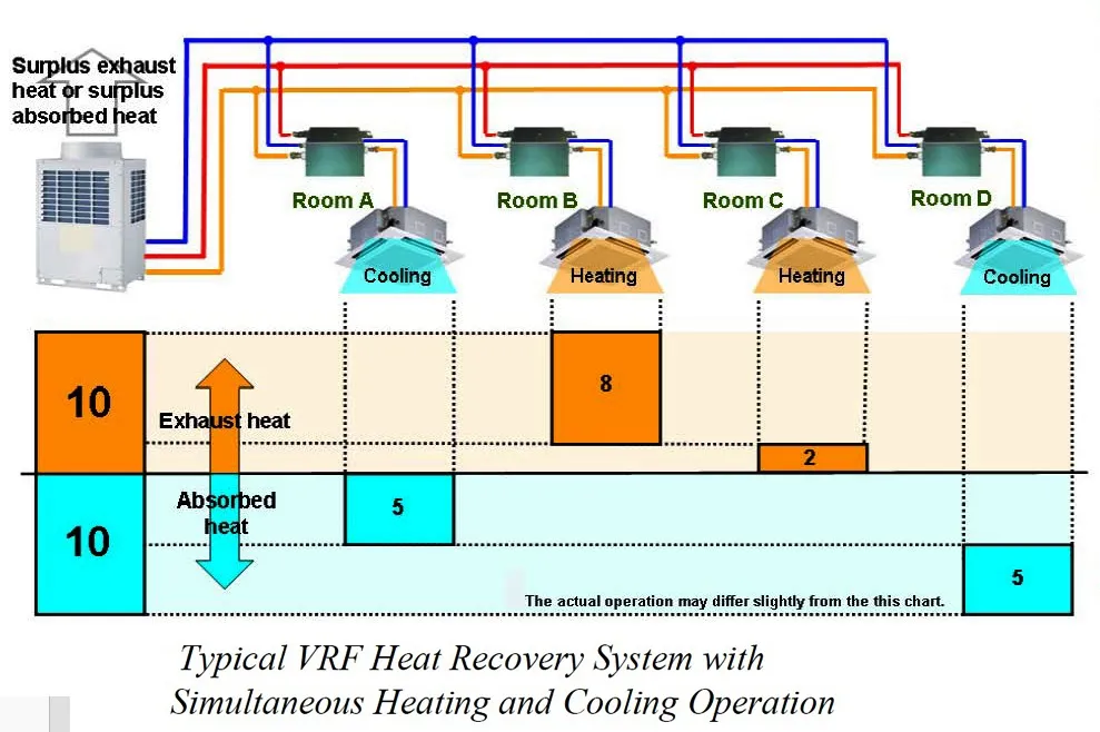
- VRF systems are available either as heat pump systems or as heat recovery systems for those applications where simultaneous heating and cooling is required.
- In addition to providing superior comfort, VRF systems offer design flexibility, energy savings, and cost-effective installation.
What’s the difference between VRV and VRF
- Many people who ask this question, mistakenly interpret it as 2 different HVAC technologies.
- Actually, those are two different terms for the same type of HVAC technology. Based on Inverter technology compressors, the first VRV HVAC systems were invented by Daikin during the early 1980’s.
- As a technology leader in the HVAC industry, Daikin had registered the VRV term (which stands for Variable Refrigerant Volume) as an official trademark.
- All other companies use VRF (Variable Refrigerant Flow) for their similar HVAC systems.
- Eventually, VRF is the more common term for these types of systems, and this is the term that will be used for the rest of the article.
1) VRF Technology
- In a VRF system, multiple indoor fan coil units may be connected to one outdoor unit.
- The outdoor unit has one or more compressors that are inverter driven, so their speed can be varied by changing the frequency of the power supply to the compressor.
- As the compressor speed changes, so does the amount of refrigerant delivered by the compressor.
- Each indoor fan coil unit has its own metering device that is controlled by the indoor unit itself, or by the outdoor unit.
- As each indoor unit sends a demand to the outdoor unit, the outdoor unit delivers the amount of refrigerant needed to meet the individual requirements of each indoor unit (As shown figure below).

- These features make the VRF system ideally suited for all applications that have part load requirements based on usage or building orientation, as well as applications that require zoning.
2) Advantages of a VRF system
Control Means Comfort
- The key to providing comfort is to supply heating or cooling when and where it is required without swings in room temperature.
- In conventional systems, the compressor is either on or off, so even spaces that have individual controls experience fluctuations in room temperature as the compressor stops and then starts again to maintain the thermostat setting (As shown in the figure below).
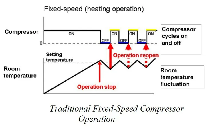
- In a VRF system, since the speed of the compressor can be varied, the compressor does not cycle on and off, but operates continuously for longer periods (As shown in the figure below).

- The required refrigerant flow is supplied to the indoor fan coil and once the set point is reached, the refrigerant flow is adjusted to maintain the room temperature smoothly without fluctuation.
- In addition to having distinct set points, the indoor unit fan speeds and louver positions can be changed to provide additional comfort in the space.
Design Flexibility
- One of the major advantages of a VRF system is the flexibility provided by the diversity of the product offering.
- Multiple types and sizes of fan coils are available to fit any application.

- Above figure shows a sample zoning layout for a VRF system, combining outdoor units, 4-way cassette type fan coils, and hi-wall type fan coils to create comfortable conditions for varying uses of 15 different spaces within the same building.
- When selecting a VRF system, keep in mind that not all systems have the same piping capabilities.
- Systems that offer expanded piping capabilities will maximize the application flexibility provided by the VRF technology.
- Important considerations when reviewing piping capabilities are:
- the maximum elevation difference allowed between the highest and lowest indoor units on a single system.
- the distance allowed from the outdoor unit to the farthest fan coil on the system.
Cost Effective Installation
- Depending on the application, the installation of a VRF system can be a cost effective alternative to traditional systems that require ductwork or large pipe sizes, and pumps and boilers in the case of chilled water systems.
- Outdoor units are light in weight and have a small footprint.
- This means that they will fit in a service elevator, so no crane is required for lifting to a rooftop installation.
- In some cases, savings on the total construction cost can be achieved since the lightweight unit means that additional support structure in the roof is not required.
Energy Savings
- All VRF systems provide energy savings by varying compressor speed and matching the output of the system as closely as possible to the load.
- In addition, VRF systems do not experience the same energy losses as systems that move conditioned air through ductwork.
- However, differences in design in the available outdoor units will influence the efficiency level that is achieved.
3) Comparison of VRF system
The VRF systems available on the market today differ according to the number and type of compressor.
The 3 types of units that will be compared here are:
- Single Variable Speed Compressor
- Variable Speed Compressor Plus Fixed- Speed Compressor
- Multiple Variable Speed Compressors
Single Variable Speed Compressor
- In this system with a single, large-capacity scroll compressor, the same compressor starts and runs when there is demand and no redundancy is available if the compressor fails.
Variable Speed Compressor Plus Fixed-Speed Compressor
- In this two-compressor system, the inverter-driven compressor always starts and ramps up until it reaches its maximum capacity at which time the fixed-speed compressor starts and the inverter- driven compressor ramps down.
- This system provides back-up capability.
Multiple Variable Speed Compressors

- Outdoor units with multiple inverter-driven twin rotary scroll compressors, as shown in figure above , offer the most complete set of advantages achievable with a VRF system.
- The system with 3 inverter-driven compressors also provides greater back-up capability. If one of the compressors fails, the system will continue to operate at 67% of its original capacity, and comfort will be maintained in the conditioned space until the faulty compressor can be replaced.
- The starting sequence of the compressors is rotated, equalizing their operating time and thereby minimizing excess operation of an individual compressor.
- Multiple inverter-driven compressors allow the unit to provide better part load performance without the need to use hot gas bypass.
- Under low-load conditions, the system has the advantage of running only as many compressors at whatever speed is required to achieve the capacity necessary to satisfy the load and maintain comfort within the conditioned space.

- Above Figure shows compares the operating status of outdoor units as changes occur in the air-conditioning loads.
- With multiple inverter-driven compressors, a better match can be made between the load in the space and the output of the compressor; the system does not waste energy generating extra capacity and at the same time provides greater comfort by eliminating room temperature fluctuations.
4) Design considerations
Unlike traditional HVAC systems, a VRF system can adjust the refrigerant flow rate to match the heating and cooling requirements of different zones or rooms in a building. This means that each zone or room can have its own temperature control, allowing for more precise temperature regulation and energy efficiency.
A VRF system typically consists of an outdoor unit, which houses the compressor and condenser, and one or more indoor units, which can be mounted on walls or ceilings to deliver cooled or heated air. The indoor units are connected to the outdoor unit by refrigerant piping and electrical wiring.
Space Layout
- The design of a VRF system begins with understanding the space layout.
- The orientation of the building and the seasons during which peak loads occur must be considered.
- The type of load (heating or cooling) and the distribution of loads into zones will depend on the intended use of the space.
- In turn, these factors will determine whether a heat pump system or heat recovery system will be the most efficient choice.

- Above figure shows a typical space layout, with zones specified as requiring heating or cooling and the load reflected in the size and type of the indoor units shown
Type of System — Heat Recovery or Heat Pump
- Heat pump and heat recovery systems both provide heating and cooling.
- A heat pump system provides either heating or cooling as required.
- A heat recovery system is ideal when simultaneous heating and cooling is required.
- The greatest efficiency will be realized when the heating and cooling loads are equal, by maximizing the amount of energy that can be transferred from one zone to another using the refrigerant, as shown in Figure below.
Size of Units
- The size of the units selected must be considered for impact on the design of the system; smaller units will provide flexibility of zoning and require less piping and less refrigerant per system.
Piping Configuration
- Flexibility of the piping options available should be considered.
- A system that provides more options for combining Y-shape joints and headers could minimize the amount of piping and refrigerant used, thus reducing the total cost of the job.
5) Installation of VRF Systems
VRF systems shall be installed as per the procedure given below.
- All piping, fittings, and insulation shall be installed to meet manufacturer’s requirements. Units shall be installed in level and plumb. Evaporator-fan components shall be installed using manufacturer’s standard mounting devices securely fastened to building structure. Refrigerant tubing and fittings shall then be installed and connected.
- Installer shall supply isolation ball valves for zoned refrigerant isolation. Installer shall supply isolation ball valves with Schrader connection for isolating refrigerant charge and evacuation at each connected inside unit and condensing unit. Isolation ball valves, with Schrader connection, are required for instances of inside unit isolation for troubleshooting, repair, or replacement without affecting the remainder of the system. These are also required at condensing unit connection to isolate unit for troubleshooting, repair or replacement and as required to provide partial capacity heating/cooling in the instance of a failure of one of the multiple outdoor units (condensing unit) compressors.
- During brazing an inert gas (such as nitrogen) shall be continuously passed through the system at a rate sufficient to maintain an oxygen free environment to prevent the formation of copper oxide scale. After piping has been completed, the refrigerant piping system shall be pressure tested at a pressure of 21 kg/cm² on the high side and 10 kg/cm² on the low side. The pressure shall be maintained on the system for a minimum of 12 h. The system shall be evacuated when the surrounding ambient air is not less than 16°C. A minimum vacuum of 500 microns of Hg shall be pulled on the system and maintained for 12 h. The vacuum pump displacement shall be not less than 4 CMH for up to 15 t. The system shall be charged as recommended by the equipment manufacturer.
- Electrical wiring, both high and low voltage, shall comply with the requirements.
- Start-up: Manufacturer or factory-authorized service representative shall be engaged to perform start-up service. Manufacturer shall provide on-site start-up and commissioning assistance through job completion. Installation and start-up checks shall be completed according to manufacturer’s written instructions. This shall include a factory start- up for factory provided control devices as well as configuring control points for other devices. Service representative shall completely configure all control devices.
- Demonstration: Manufacturer or factory- authorized service representative shall also be engaged to train owner’s maintenance personnel to adjust, operate and maintain individual units and complete system. This shall include training of the owner’s energy management department representatives.
- The indoor units and outside condensing units shall be installed in accordance with the manufacturer’s recommendations and as shown on the shop drawings.
6) Conclusion
- A VRF system offers flexible installation and energy-saving cooling and heating comfort and should be considered as an alternative to traditional systems for those applications where zoning or part load operation is required.
and ability to provide individualized comfort control. However, they can be more expensive to install than traditional HVAC systems, and they require professional installation and maintenance.